2 - 20 MC67 Integrator Guide
2. Route the power input cable from the cradle’s power port to the connection point for the vehicle’s power
source.
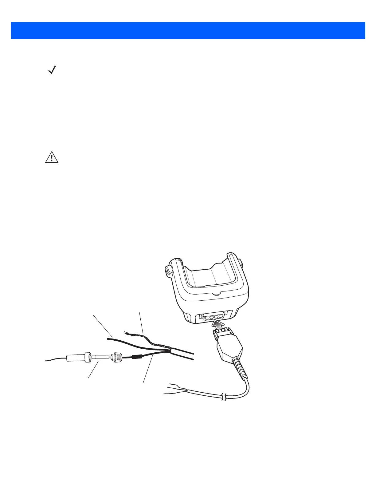
3. When using the supplied in-line fuse holder (which must be used if not connecting to vehicle’s fuse panel):
a. Ensure the fuse holder contains a 5A UL Listed slow-blow fuse.
b. Splice the fuse holder to the end of the red V+ wire, as shown above. Make the distance from the fuse
to the power connection point as short as possible.
Figure 2-22
Vehicle Cradle Power Connection
4. Prepare the cable termination.
a. Red wire: connect to a +12/24 V vehicle power source.
b. Black wire and Shield wire: connect to vehicle ground wire or chassis ground.
NOTE The ideal location for connecting the vehicle cradle power input cable would be an accessory output in
your vehicle’s fuse panel. The vehicle cradle should be added to a circuit with a maximum load capacity
for the cradle and the original circuit. Refer to the vehicle’s Owner’s Manual for identification of the circuit.
If a fused output is not available, the vehicle cradle must be installed with the provided in-line fuse holder
and UL Listed 5A fuse. The fuse protects the vehicle from an electrical short on the power line to the
cradle.
To use the cradle to charge the MC67 and spare battery, when the vehicle’s ignition is off, connect the
cradle to unswitched power.
CAUTION The means of routing and securing the power input cable from the cradle through to the vehicle power
source is extremely important. Hazards associated with improper wiring can be severe. To avoid
unintentional contact between the wire and any sharp edges, provide the cable with proper bushings
and clamping where it passes through openings. If the wire is subjected to sharp surfaces and excess
engine vibration, the wiring harness insulation can wear away, causing a short between the bare wire
and chassis. This can start a fire.
To avoid any mishaps, all wiring should be routed away from moving parts, high temperature areas and
any contaminants.
Shield Wire
(bare wire)
Ground
Wire (black)
V+ Power (red)
5A Fuse and
Fuse Holder