212 Actual signals and parameters
DI1(INV) User parameter set control through inverted digital input
DI1. Falling edge of inverted digital input DI1: User
parameter set 2 is loaded into use. Rising edge of inverted
digital input DI1: User parameter set 1 is loaded into use.
-1
DI2(INV) See selection DI1(INV).-2
DI3(INV) See selection DI1(INV).-3
DI4(INV) See selection DI1(INV).-4
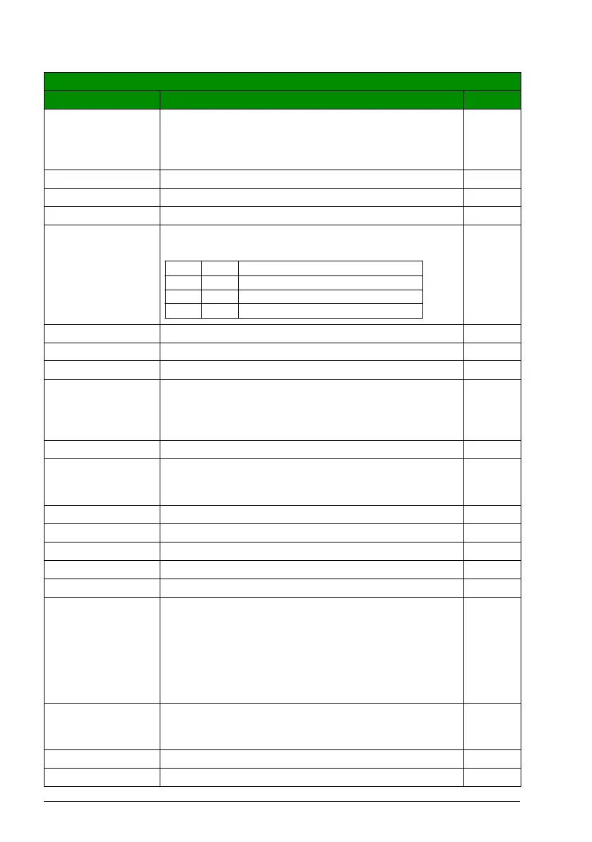
DI1,2(INV) User parameter set selection through inverted digital inputs
DI1 and DI2. 1 = DI inactive, 0 =DI active.
-7
DI2,3(INV) See selection DI1,2.-8
DI3,4(INV) See selection DI1,2.-9
DI4,5(INV) See selection DI1,2.-10
1606 LOCAL LOCK Disables entering local control mode or selects the source
for the local control mode lock signal. When local lock is
active, entering the local control mode is disabled
(LOC/REM key of the panel).
NOT SEL
NOT SEL Local control is allowed. 0
DI1 Local control mode lock signal through digital input DI1.
Rising edge of digital input DI1: Local control disabled.
Falling edge of digital input DI1: Local control allowed.
1
DI2 See selection DI1.2
DI3 See selection DI1.3
DI4 See selection DI1.4
DI5 See selection DI1.5
ON Local control is disabled. 7
COMM Fieldbus interface as the source for the local lock, ie,
Control word 0301 FB CMD WORD 1 bit 14. The Control
word is sent by the fieldbus controller through the fieldbus
adapter or embedded fieldbus (Modbus) to the drive. For
the Control word bits, see section DCU communication
profile on page 333.
Note: This setting applies only for the DCU profile.
8
DI1(INV) Local lock through inverted digital input DI1. Rising edge of
inverted digital input DI1: Local control allowed. Falling edge
of inverted digital input DI1: Local control disabled.
-1
DI2(INV) See selection DI1(INV).-2
DI3(INV) See selection DI1(INV).-3
All parameters
No. Name/Value Description Def/FbEq
DI1 DI2 User parameter set
1 1 User parameter set 1
0 1 User parameter set 2
1 0 User parameter set 3

 Loading...


