254 Actual signals and parameters
FAULT The drive trips on fault UNDERLOAD (0017) and the motor
coasts to stop.
Note: Set parameter value to FA U LT only after the drive ID
run is performed! If FAULT is selected, the drive may
generate an UNDERLOAD fault during ID run.
1
ALARM The drive generates alarm UNDERLOAD (2011). 2
3014 UNDERLOAD
TIME
Defines the time limit for the underload function. See
parameter 3013 UNDERLOAD FUNC.
20 s
10…400 s Time limit 1 = 1 s
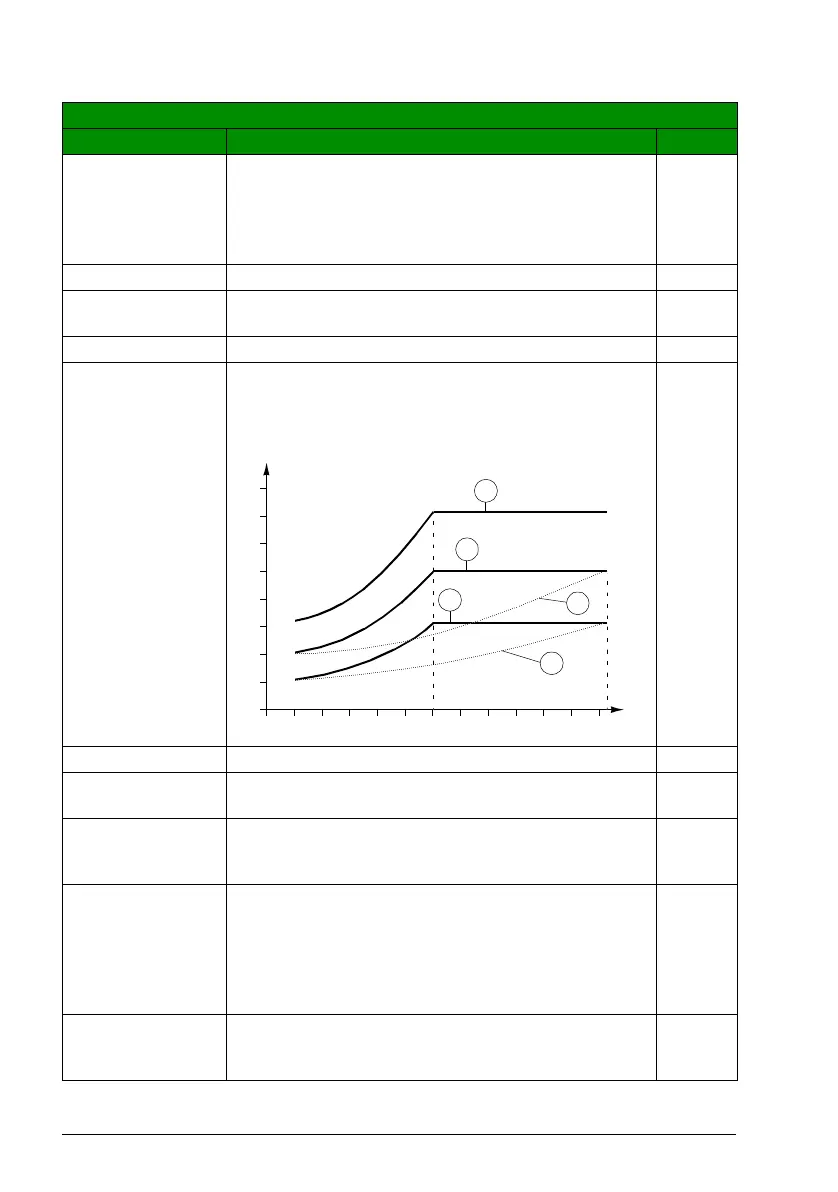
3015 UNDERLOAD
CURVE
Selects the load curve for the underload function. See
parameter 3013 UNDERLOAD FUNC.
1
1…5 Number of the load curve type in the figure 1 = 1
3016 SUPPLY
PHASE
Selects how the drive reacts to supply phase loss, ie, when
DC voltage ripple is excessive.
FA U LT
FAULT The drive trips on fault SUPPLY PHASE (0022) and the
motor coasts to stop when the DC voltage ripple exceeds
14% of the nominal DC voltage.
0
LIMIT/ALARM Drive output current is limited and alarm INPUT PHASE
LOSS (2026) is generated when the DC voltage ripple
exceeds 14% of the nominal DC voltage.
There is a 10 s delay between the activation of the alarm
and the output current limitation. The current is limited until
the ripple drops under the minimum limit, 0.3 · I
hd
.
1
ALARM The drive generates alarm INPUT PHASE LOSS (2026)
when the DC ripple exceeds 14% of the nominal DC
voltage.
2
All parameters
No. Name/Value Description Def/FbEq
T
M
T
M
= nominal torque of the motor
ƒ
N
= nominal frequency of the motor (9907)
3
2
1
5
4
Underload curve types
70%
50%
30%
80
60
40
20
0
(%)
2.4
·
f
N
f
N
f

 Loading...


