5.6 DISCRETE INPUT MODULES (DI0-17)
The Discrete Input Modules (DI0-17) generate logic levels based on the applied voltages or contact condition on the associated termi-
nals. Inputs DI2-17 are active only when the appropriate hardware options are installed. The 18 Discrete Input Modules are provided in
Table 5-6. Each one can be configured separately (total combined DIs and DOs for controller cannot exceed 18).
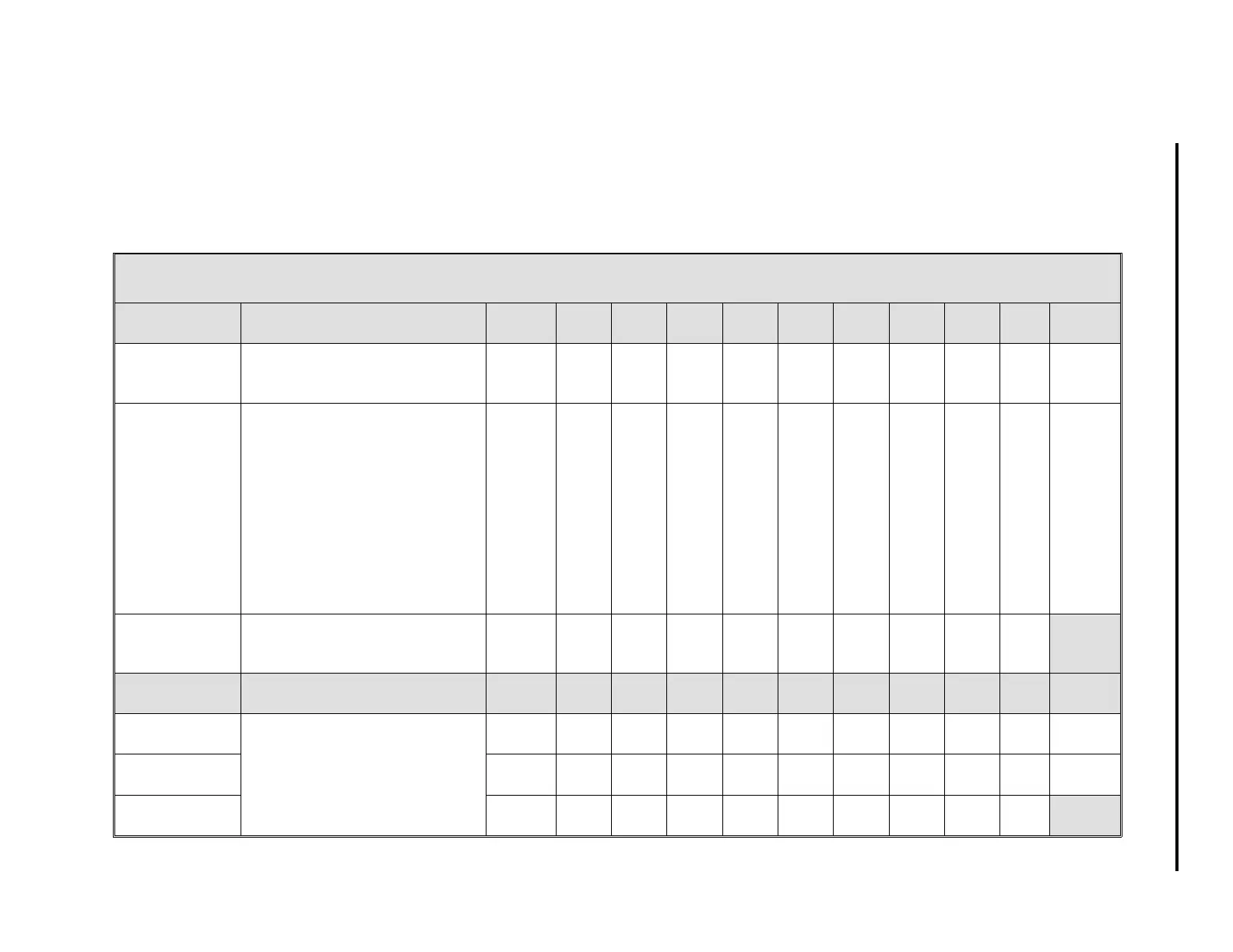
Table 5-6. Discrete Input Modules (DI0-17)
Title Definition Atom DI
0
DI
1
DI
2
DI
3
DI
4
DI
5
DI
6
DI
7
DI
8
Default
Discrete Input This is an indication of the
applied signal level after
INV
conditioning (see below).
DI
(0-8)
L000 L001 L002 L003 L004 L005 L006 L007 L008 0
Input Invert This parameter specifies the
signaling protocol to use for the
DI
value (see above):
0
- 1-ON
1
- 0-ON
Input: Open, 4-24VDC (OFF)
INV 0, 1-ON DI=0
INV 1, 0-ON DI=1
Input: Closed, <1VDC (ON)
INV 0, 1-ON DI=1
INV 1, 0-ON DI=0
INV
(0-8)
L264 L265 L266 L267 L268 L269 L270 L271 L272 0
Tag Name It is an assignable 10 character
name for the contact control
input.
TAG A262A263A264A265A266A267A268A269A270
Title Definition Atom DI
9
DI
10
DI
11
DI
12
DI
13
DI
14
DI
15
DI
16
DI
17
Default
Discrete Input
Same as above.
DI
(9-17)
L009 L010 L011 L012 L013 L014 L015 L016 L017 0
Input Invert INV
(9-17)
L273 L274 L275 L276 L277 L278 L279 L280 L281 0
Tag Name TAG A271 A272 A273 A274 A275 A276 A277 A278 A279
5-9
Section 5. Configuration Parameters