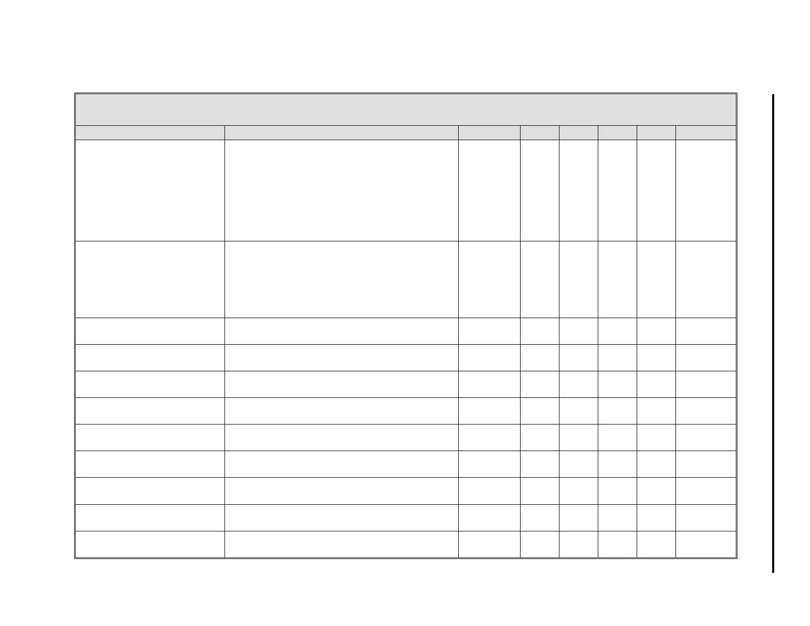
Table 5-9. Controller Modules (CON0-3)
Title Definition Atom CON0 CON1 CON2 CON3 Default
Manual Fallback Disable
0
- OFF
1
- ON
A value of
1
during power-up means the
controller auto/manual selector remains
unchanged from when power was removed. A
value of
0
causes the controller to always
power-up with the selector in the manual
position.
MFD
(0-3)
L120 L144 L168 L192 0
Hard Manual Limit
0
- OFF
1
- ON
A
1
causes the Output High and Low Limits
(OH, OL) to be applied to the output in manual
operation.
0
means the output value is not
limited in manual operation.
HML
(0-3)
L122 L146 L170 L194 1
Control Track Command Used internally by the controller. CTC
(0-3)
L123 L147 L171 L195 0
Control Alarm Acknowledge Used internally by the controller. AK
(0-3)
L125 L149 L173 L197 0
Alarm AA Past State Used internally by the controller. LA
(0-3)
L126 L150 L174 L198 0
Alarm AB Past State Used internally by the controller. LB
(0-3)
L127 L151 L175 L199 0
Process Variable The process variable used in the PID algorithm. PV
(0-3)
C100 C136 C172 C208 0
Setpoint The output of the setpoint generator. SP
(0-3)
C101 C137 C173 C209 0
Output The output of the Auto/Manual Selector. OUT
(0-3)
C102 C138 C174 C210 0
Alarm Limit 1 This parameters is the point (in engineering
units) where an alarm is triggered.
PL1
(0-3)
C103 C139 C175 C211 100
Alarm Limit 2 This parameters is the point (in engineering
units) where an alarm is triggered.
PL2
(0-3)
C104 C140 C176 C212 0
6 of 9
5-19
Section 5. Configuration Parameters