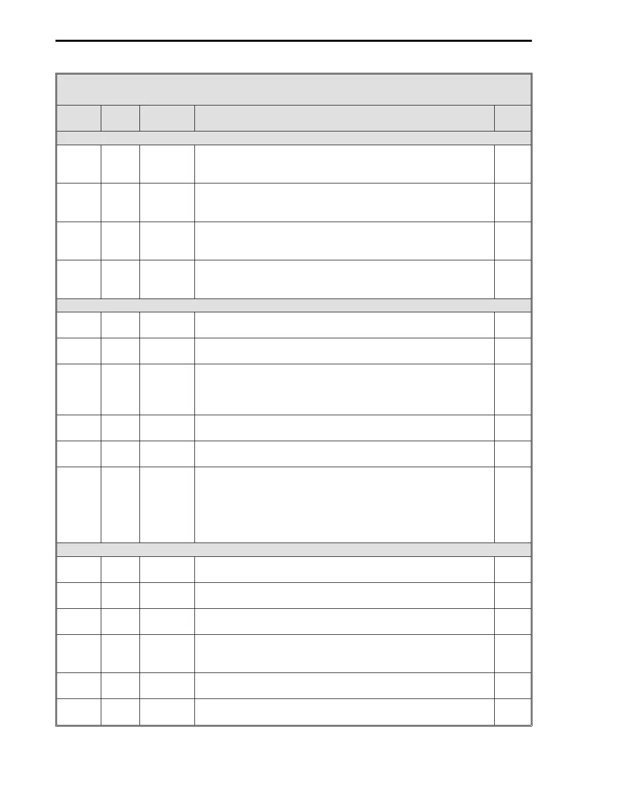
Table 11-3. CS20 Two Loop Controller Datapoints
Data-
point Table Module Title and Function
De-
fault
AI3 - Remote Setpoint Loop 2 (Is affected by Setpoint Related Datapoints) (Cont)
C279 5-4 AI3 Engineering Zero - Enter a value that represents in
engineering units the Loop 2 Remote Setpoint lower range
signal value.
0
B272 5-4 AI3 Digital Filter Index - This is a first order filter that can be
applied to the Loop 2 Remote Setpoint signal. See Table 5-4
for input values.
3
L419 5-4 AI3 0-5 V Input - Enter a value that matches the signal voltage
range of the Loop 2 Remote Setpoint signal. 1 = 0 - 5 V
input range; 0 = 1 - 5 V input range.
0
L443 5-4 AI3 Square Root Signal - It is used if the Loop 2 Remote Setpoint
input is a squared signal value that must be linearized. 0 =
input is already linear; 1 = square root to restore linearization.
0
AO0 - Control Output Loop 1
L472 5-5 AO0 0-20 mA Output - 0 = 4-20 mA signal; 1 = 0-20 mA signal.
Enter a value to match the Loop 1 output valve requirements.
0
L120 5-9 CON0 Manual Fallback Disable - 0 = always power up in manual for
Loop 1; 1 = auto/manual selector unchanged at power up.
0
L122 5-9 CON0 Hard Manual Limit - 1 = apply output limits to the final output
of the Auto-Manual Generator for Loop 1. It affects both the
manual push buttons and the controller’s result. 0 = do not
apply limits.
1
C109 5-9 CON0 Output High Limit - Sets maximum Loop 1 Control Output
signal value for in engineering units.
100
C110 5-9 CON0 Output Low Limit - Sets minimum Loop 1 Control Output
signal value in engineering units.
0
C118 5-9 CON0 Output Slew Rate - It is a rate limit applied to the output
value. When configured to a non-zero value, the output from
the Auto-Selector for Loop 1 is only allowed to change by
this amount each scan time. A zero disables output slewing.
It does not affect manual operation.
0
CON0 Control Loop 1 Related Datapoints
C106 5-9 CON0 Proportional Band - Is the Loop 1 percent of error required to
move the output full scale for proportional action.
100
C107 5-9 CON0 Reset Time - Is the number of minutes per repeat of integral
action for Loop 1. It is mutually exclusive with Manual Reset.
0
C108 5-9 CON0 Rate Time - Represents the minutes Loop 1 proportional
action is advanced.
0
C111 5-9 CON0 Manual Reset - It determines Loop 1 output valve position
when the controller is in Auto and the error = 0. It is mutually
exclusive with Reset Time.
50
L106 5-9 CON0 Reverse Switch - 0 = Loop 1 Control Output
↑
if Loop 1 PV
↑
; 1 = Loop 1 Control Output
↓
if Loop 1 PV
↑
.
1
L114 5-9 CON0 Auto Enable - Controller output is from the Loop 1 PID
algorithm when set to 1 and A/M push button is in Auto.
1
3 of 6
53MC5000 Process Control Station
11-8