Shielding example
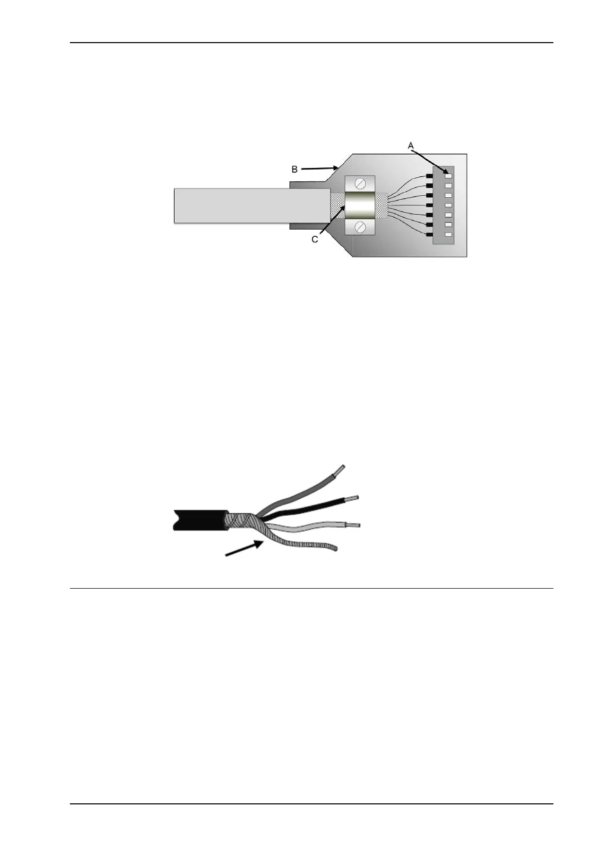
The below example shows the shielding of a d-type connector:
xx1700001320
A A dimpled connector body makes multiple bonds to the mating connector
body all around its periphery, 360° bonding.
B Metal, or metallized, back shell makes 360° bond to the connector body.
C The cable shield is exposed and 360° clamped to the back shell. A tight fit
is a must.
Many other 360° bonding methods and types of 360° shielded connectors are also
acceptable.
Shield pigtail termination
Shield pigtail termination, as shown below, shall be avoided. If a pigtail connection
cannot be avoided, make it as short as possible.
xx1700001321
Ground and screen connections
The task of the grounding system is twofold - protective and functional. The primary
task is to serve as protective earth (PE) for personal and equipment safety. The
secondary task is to serve as a return path for common mode current.
For further information refer to EN 60204-1 and UL 1740.
Grounding requirements
The controller cabinet ground must come from the mains power supply PE.
• The grounding cable color shall be green-yellow.
• The ground for the controller cabinet, robot manipulator and peripheral
devices must be the same, preferably an equipotential ground grid (mesh).
Continues on next page
Product manual - OmniCore V250XT 71
3HAC073447-001 Revision: B
© Copyright 2020-2022 ABB. All rights reserved.
3 Installation and commissioning
3.5.2 Connecting cables to the controller
Continued