• Ground connection points must have stable inter-metallic bonding, like screw
fixation. Paint, dirt, rust, and other insulating material must be removed from
the contacting surfaces.
For requirements on the marking of the supply ground connection inside the control
cabinet refer to UL 508C. For further details on how grounding systems should be
designed refer to IEC 61000-5-2. For details of cross-sectional area of PE refer to
IEC 60204-1.
Grounding installation
For information on how to connect protective earth to the OmniCore controller
cabinet, see Connecting incoming mains and protective earth to the controller on
page 77.
For information on how to connect protective earth for the manipulator, see the
corresponding product manual.
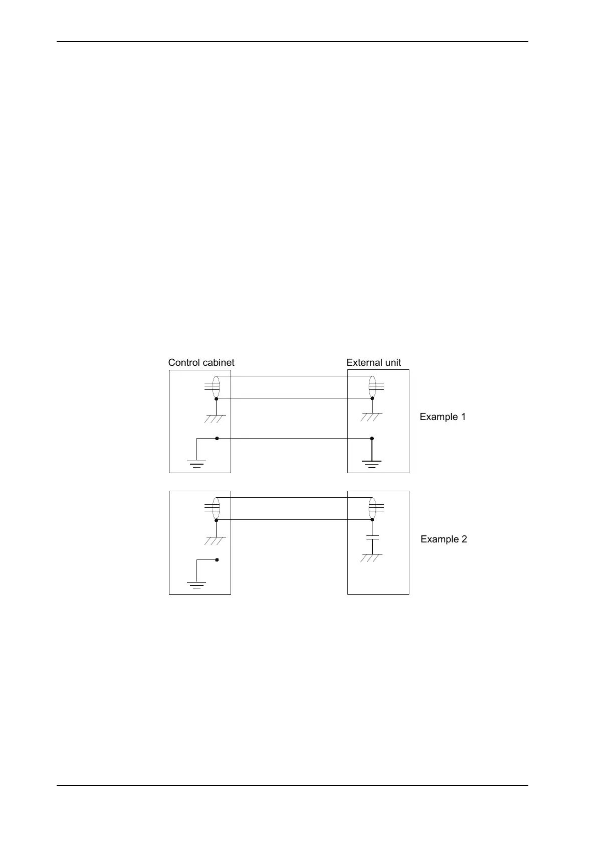
Examples
The following figure shows 2 examples on how protective earth and the signal
cable screens can be connected:
Control cabinet
External unit
Example 1
Example 2
xx1200000960
Example 1:
• Where a good earth connection is available on all units, the best shielding
is obtained by grounding all screens at both ends on all units.
Example 2:
• If the cable is terminated where a good earth connection is not available a
noise suppression capacitor can be used. The screens of the 2 cables must
be connected as shown in the figure, but not connected to the chassis of the
unit.
Continues on next page
72 Product manual - OmniCore V250XT
3HAC073447-001 Revision: B
© Copyright 2020-2022 ABB. All rights reserved.
3 Installation and commissioning
3.5.2 Connecting cables to the controller
Continued