-EN Rev. E Operating instruction SCK Gas Sampling System 107
Proceed as follows to connect internal electric lines:
Step Procedure
1
On the control cabinet: Turn off the main switch.
2
Install internal lines in accordance with the electrical connec-
tion plan (see appendix). This applies to:
24 VDC control cabinet-cooling module line
230/400 VAC cable to cooling-water pump
230/400 VAC cable to heat exchanger fan motor
24 VDC cable to probe retractor
24/26/28/30 VAC cable to probe retractor (option "H")
230 VAC cable to probe heating (option "60S")
230 VAC cable to probe retractor
Signal cable to analyzer cabinet
System bus cable control cabinet - cooling module (see step
3)
System bus cable probe retractor - cooling module (see step
3)
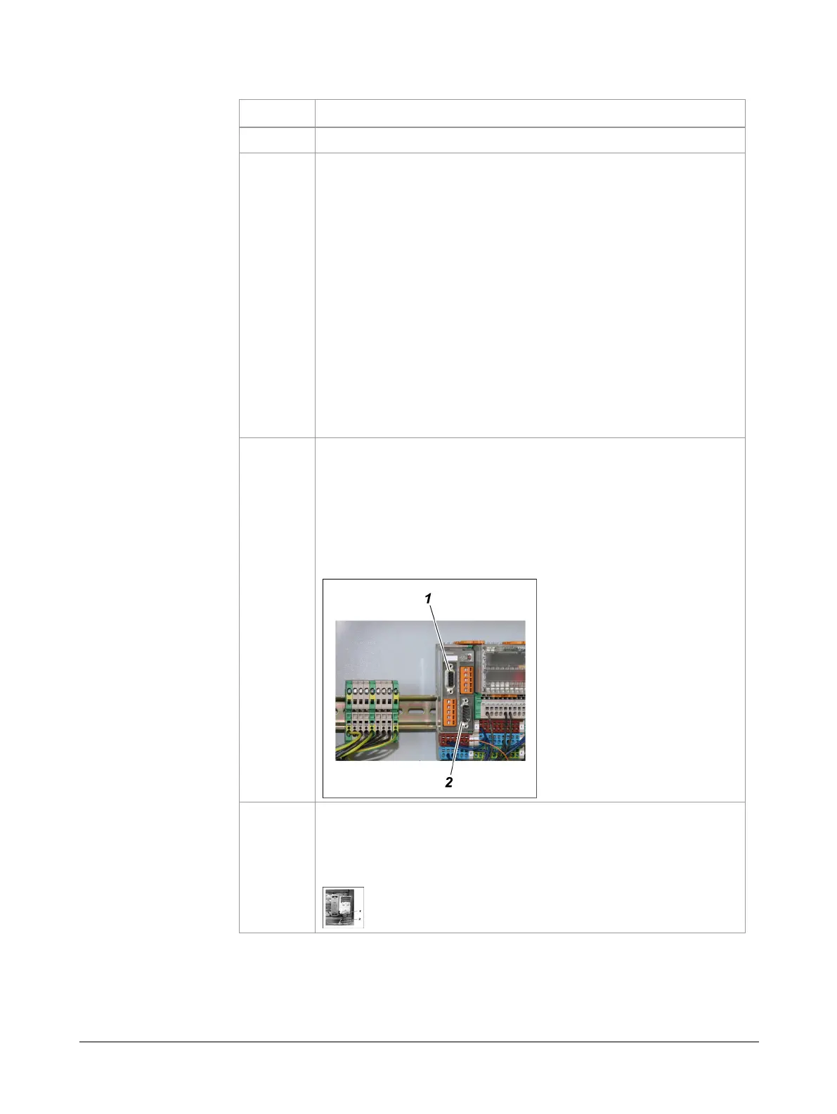
3
Connecting the system bus cable:
Install system bus cable from control cabinet to cooling
module terminal box. Connect to the 9-pin D-Sub connector
of the CAN bridge
.
Install system bus cable from the probe retractor terminal
box to the cooling module terminal box. Connect to the 9-
pin D-Sub connector of the CAN bridge
.
4
Connecting the system bus cable to the frequency converter:
Loosen the short system bus cable with T-piece
from its
transport fixing and connect it to the CAN adapter
at the
frequency converter.