18 Operating instruction SCK Gas Sampling System OI/SCK-EN Rev. E
Structure and function
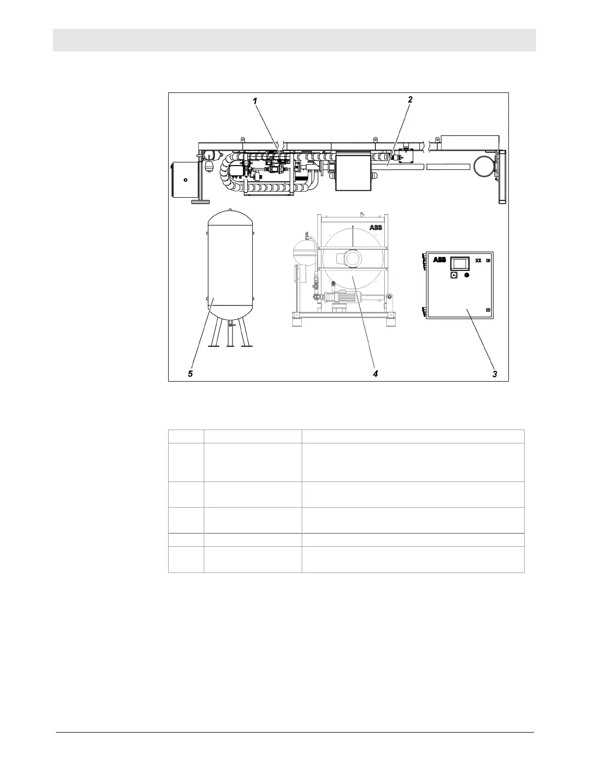
The following diagram shows an overview of the SCK modules:
The individual modules of the gas sampling system have the following func-
tions:
mechanical movement of the probe
automatic removal of the probe when
sampling of sample gas from the
process
cooling of the gas sampling probe
Compressed-air
tank (optional)
back up probe movement if the on-
site compressed-air supply fails
The sampling system serves the purpose of continuous sampling of sample
gas at the measuring point, i.e. at the gas outlet of the rotary kiln or at the
gas outlet of the calcinator. The probe forms a unit with the pneumatic probe
retractor. It is integrated in a closed cooling-water circuit with a heat ex-
changer (cooling module). The retractor and probe can be controlled from the
touchscreen on the control cabinet. The sample gas is filtered in the probe
and ducted into the sample gas line. Further conditioning and analysis of the
gas takes place in external equipment (not part of the gas sampling system).
Illustration
Modules
explanations