SensyMaster FMT430, FMT450 THERMAL MASS FLOWMETER | OI/FMT430/450-EN REV. B 67
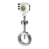
Single-compartment housing
Signal cable to sensor
Terminals for power supply
Terminals for inputs and outputs (base device)
Terminals for signal cable
Terminals for inputs and outputs (plug-in cards)
Terminal for potential equalization
LCD indicator
Bracket for LCD indicator (park position)
Figure 61: Electrical connection to transmitter in remote mount design [example, dimensions in mm (in)]
If the O-ring gasket is seated incorrectly or damaged, this
may have an adverse effect on the housing protection class.
Follow the instructions in Opening and closing the housing
on page 47 to open and close the housing safely.
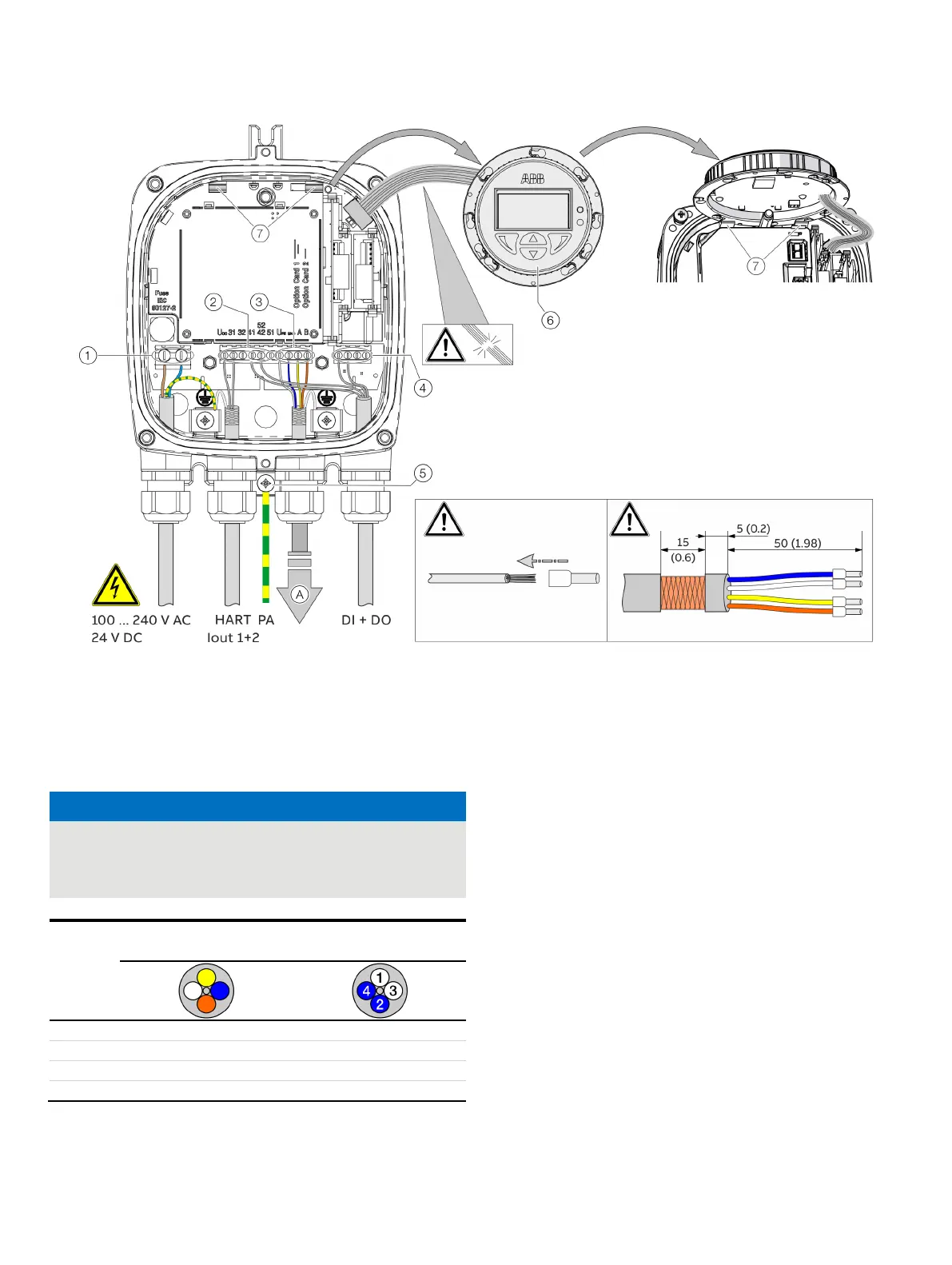
ABB signal cable
HELKAMA signal cable
Blue Blue (4)
Yellow Blue (2)
Observe the following points when connecting to an electrical
supply:
• Lead the cable for the power supply and the signal inputs
and outputs into the housing as shown.
• The signal cable to the sensor is connected in the lower
connection area of the transmitter.
• Connect the cables in accordance with the electrical
connection diagram. If present, connect the cable shielding
to the earthing clamp provided.
• Use wire end ferrules when connecting.
• After connecting the power supply, terminal cover
2
must be installed.
• Close unused cable entries using suitable plugs.