72 SensyMaster FMT430, FMT450 THERMAL MASS FLOWMETER | OI/FMT430/450-EN REV. B
8 Commissioning
Safety instructions
Danger of explosion if the device is operated with the
transmitter housing or terminal box open!
Before opening the transmitter housing or the terminal box,
note the following points:
• A valid fire permit must be present.
• Make sure that there is no explosion hazard.
• Switch off the power supply and wait for t > 20 minutes
Risk of burns due to hot measuring media
The device surface temperature may exceed 70 °C (158 °F),
depending on the measuring medium temperature!
• Before starting work on the device, make sure that it has
Aggressive or corrosive media may lead to the damage of
wetted parts of the sensor. As a result, measuring medium under
pressure can leak out.
Wear to the flange gasket or process connection gaskets
(e.g. flange fitting or pipe fitting) may cause a pressurized
measuring medium to escape.
If pressure surges above the permissible nominal pressure of the
device occur permanently during operation, this may affect the
service life of the device.
If there is a chance that safe operation is no longer possible,
take the device out of operation and secure it against
unintended startup.
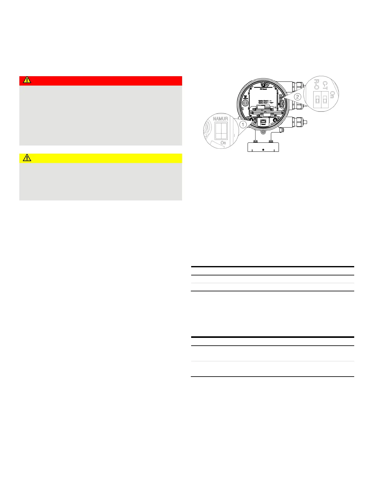
Hardware settings
Dual- compartment housing
NAMUR DIP switch
Write protection DIP switch
Figure 65: Position of the DIP switches
DIP switches are located behind the front housing cover. The DIP
switches are used to configure specific hardware functions. The
power supply to the transmitter must be briefly interrupted in
order for the modified setting to take effect.
Write-protect switch
When write protection is activated, device parameterization
cannot be changed via the LCD indicator. Activating and sealing
the write protection switch protects the device against
tampering
Write protection deactivated.
Configuration of digital outputs 41 / 42 and 51 / 52
The configuration (NAMUR, optoelectronic coupler) for the
digital outputs on the basic device is set via DIP switches in the
transmitter.
Digital output 41 / 42 and 51 /
Digital output 41 / 42 and 51 /
52 as
optoelectronic coupler output.