SensyMaster FMT430, FMT450 THERMAL MASS FLOWMETER | OI/FMT430/450-EN REV. B 55
Cable entries
The electrical connection is made via cable entries with a ½ in-
NPT or M20 × 1.5 thread.
Devices with a M20 × 1.5 or ½ in-NPT thread are equipped with
protective plugs.
The black protective plugs in the cable glands are intended to
provide protection during transport.
Any unused cable entries must be sealed with sealing plugs
before commissioning in accordance with the applicable
national standards.
• Observe maximum torque of 4.5 Nm (3.3 ft lb) when
tightening the M20 cable gland.
• Make sure that the cable outer dimension used will fit the
clamping range of the cable gland.
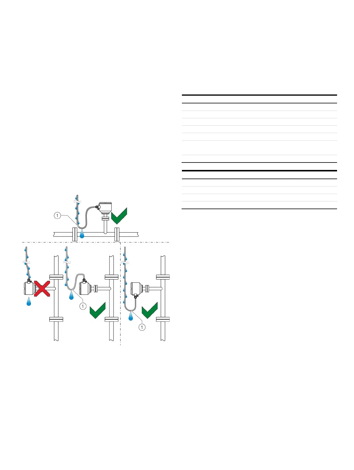
Installing the connection cables
Ensure that a drip loop (water trap) is used when installing the
connecting cables for the sensor.
Drip loop
Figure 40: Laying the connection cable
Signal cable
The signal cable used for the connection of the transmitter and
sensor must fulfill at least the following technical specifications.
100 to 120
6 to 12 mm (0.24 to 0.47
Two wire pairs as a star-quad cable
-section Length-
Copper braid with approximately 85 %
coverage
Maximum signal cable length
mm
2
(AWG 24) 25 m (82
2
mm
2
(AWG 20) 65 m (213
2
Recommended cables
It is recommended to use an ABB signal cable with the order
number 3KQZ407123U0100 for standard applications.
The ABB signal cable fulfills the above-mentioned cable
specification and can be utilized unrestrictedly up to an ambient
temperature of T
amb.
= 80 °C (176 °F).