70 SensyMaster FMT430, FMT450 THERMAL MASS FLOWMETER | OI/FMT430/450-EN REV. B
… 7 Electrical connections
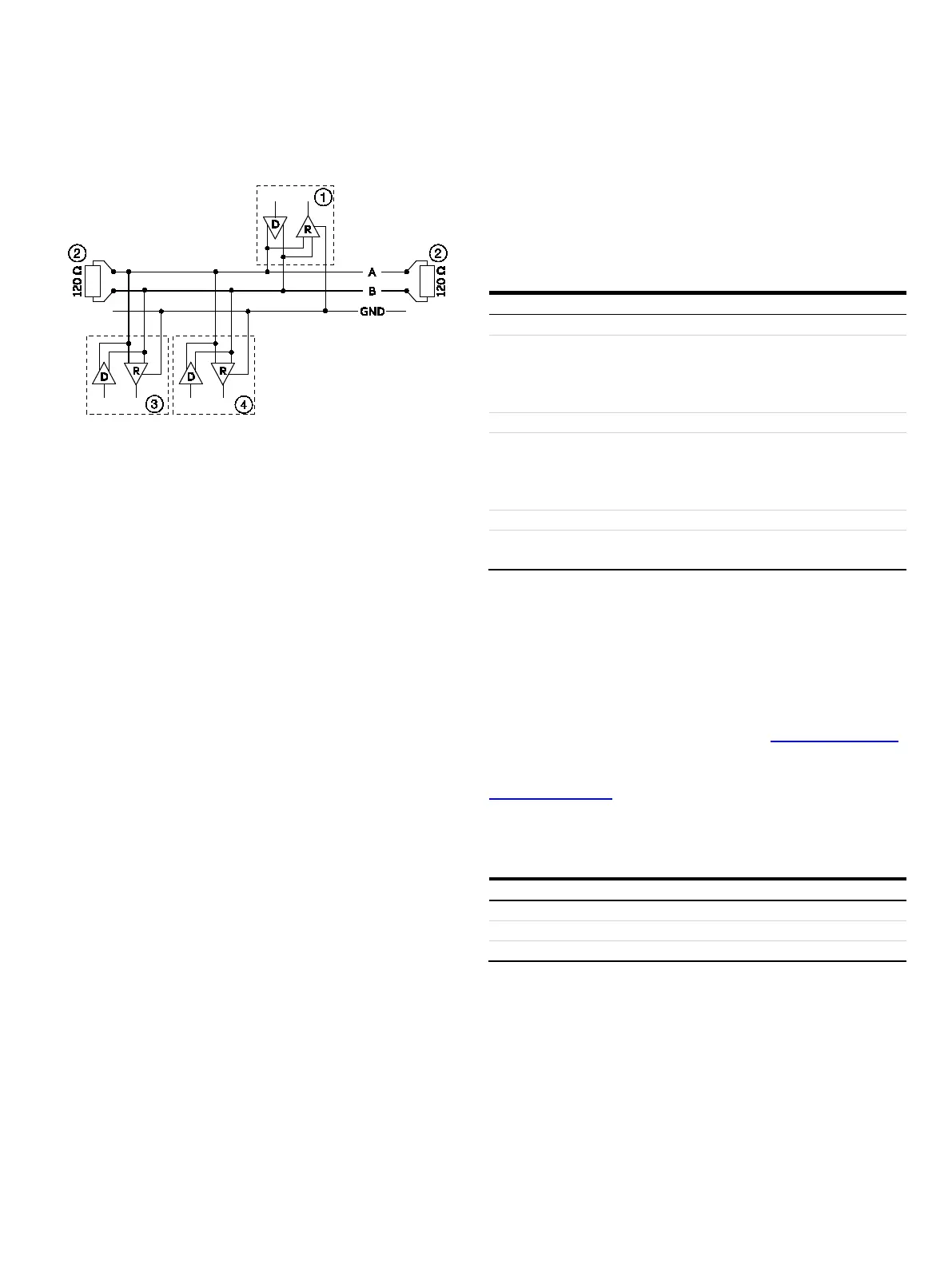
… Digital communication
Modbus master
Terminating resistor
Modbus slave 1
Modbus slave n to 32
Figure 63: Communication with the Modbus protocol
Cable specification
The maximum permissible length is dependent on the baud rate,
the cable (diameter, capacity and surge impedance), the number
of loads in the device chain, and the network configuration
(2-core or 4-core).
• At a baud rate of 9600 and with a conductor cross-section of
at least 0.14 mm
2
(AWG 26), the maximum length is 1000 m
(3280 ft).
• When using a 4-core cable as a 2-wire wiring system, the
maximum length must be halved.
• The spur lines must be short, a maximum of 20 m (66 ft).
• When using a distributor with ‘n’ connections, each branch
must have a maximum length of 40 m (131 ft) divided by ‘n.’
The maximum cable length depends on the type of cable used.
The following standard values apply:
• Up to 6 m (20 ft):
cable with standard shielding or twisted-pair cable.
• Up to 300 m (984 ft):
double twisted-pair cable with overall foil shielding and
integrated earth cable.
• Up to 1200 m (3937 ft):
double twisted-pair cable with individual foil shielding and
integrated earth cables. Example: Belden 9729 or equivalent
cable.
A category 5 cable can be used for Modbus RS485 up to a
maximum length of 600 m (1968 ft). For the symmetrical pairs in
RS485 systems, a surge impedance of more than 100 Ω is
preferred, especially at a baud rate of 19200 and above.
PROFIBUS DP® communication
Note
The PROFIBUS DP® protocol is an unsecured protocol, as such
the intended application should be assessed to ensure that
these protocols are suitable before implementation.
/ V2
DP interface or via the local
operating interface in connection with Asset Vision
Basic (DAT200) and a
corresponding Device Type
61158-2
9.6 kbps, 19.2 kbps, 45.45 kbps, 93.75 kbps, 187.5
kbps, 500 kbps, 1.5 Mbps
The baud rate is automatically detected and does not
need to be configured manually
to 126
Only one of the three different GSD files provided by ABB is
needed for commissioning.
Parameterization of the device can be performed via the display,
or through a device driver in the form of an EDD (Electronic
Device Description) or DTM (Device Type Manager).
You can download EDD, DTM and GSD from www.abb.com/flow.
The files required for operation can also be downloaded from
www.profibus.com.
ABB provides three different GSD files which can be integrated in
the system.
1
Users decide at system integration whether to install the full
range of functions or only part. Switching is made using the
‘Ident Nr. Selector’ parameter.
Refer to Ident Nr. Selector on page 121.