SensyMaster FMT430, FMT450 THERMAL MASS FLOWMETER | OI/FMT430/450-EN REV. B 43
Calculation of the installation length X and installation depth Y
Outside length of the integrated changing device
Installation depth of the integrated changing device
Sensor length
Outside diameter of the pipeline
Example
• Sensor length h = 425 mm (16.73 in)
• Pipe with outside diameter of 210 mm (8.27 in)
• The hot tap fitting is in measurement position
X = 425 mm − (210 mm / 2) = 320 mm
Y = (210 mm / 2) − 28 mm = 77 mm
Consider the following points when installing the welding
version in the piping:
• Maintain a right angle to the pipe axis (max. tolerance 2°).
• The adapter centering pin must be aligned with the pipe
axis in the flow direction (outflow side, behind the
measuring point).
Damage to components
If the welded joints become hot, warping of the sealing
surfaces and / or damage to the O-rings can occur.
• Pause occasionally to allow the fitting to cool.
Impact on measuring accuracy
Deviations from the stated dimension and position tolerances
have an impact on measuring accuracy.
Installing the sensor
When installing the sensor, observe the following points:
• Installation in the pipe component or welding adapter is
only possible if the sensor data matches the measuring
point specifications.
• The sensor may be sealed only by using the O-ring
supplied in the scope of delivery. The O-ring must be
placed in the designated groove on the sensor
connection.
• The sensor elements may not be damaged when inserting
the sensor into the pipe component.
• If you are using an integrated hot tap fitting, you must
check that the hot tap fitting is in the disassembly
position before releasing the fixing screws.
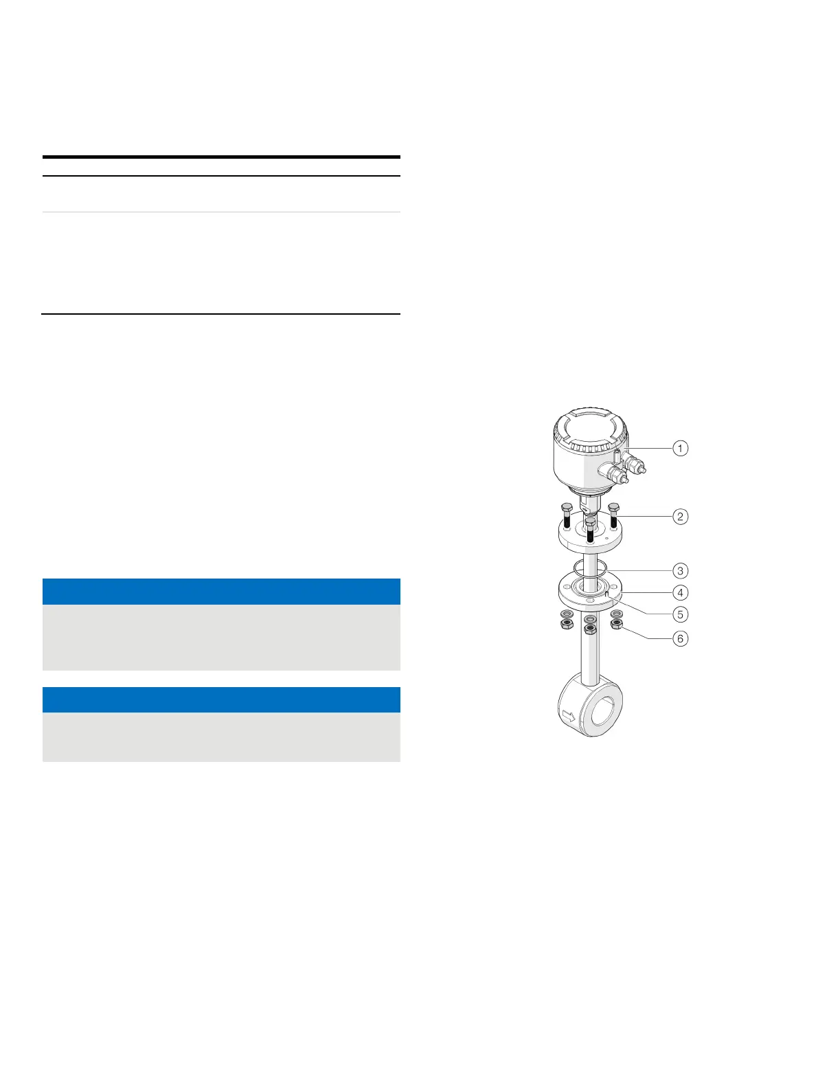
Wafer type design and welding adapter
Sensor
Flange screws
O-ring
Sensor connection
Centering pin
Washers and nuts
Figure 28: Installing a sensor (example)