62 SensyMaster FMT430, FMT450 THERMAL MASS FLOWMETER | OI/FMT430/450-EN REV. B
… 7 Electrical connections
… Electrical data for inputs and outputs
Connection examples
Input and output functions are configured via the device
software in accordance with the desired application.
Parameter descriptions on page 96
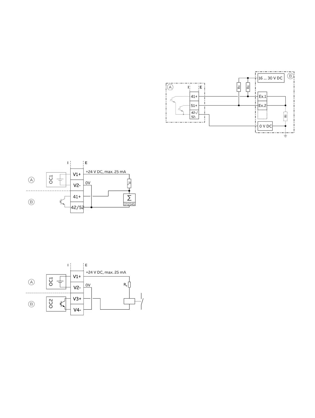
Digital output 41 / 42, 51 / 52, V3 / V4 active
When the ‘loop power supply 24 V DC (blue)’ plug-in card is used,
the digital outputs on the basic device and on the option
modules can also be wired as active digital outputs.
Note
Each ‘loop power supply (blue)’ plug-in card must only power one
output.
It must not be connected to two outputs (for example digital
output 41 / 42 and 51 / 52)!
‘Loop power supply (blue)’ plug-in card in slot 1
Digital output, digital output 41 / 42
Figure 53: Active digital output 41 / 42 (example)
The connection example shows usage for digital output 41 / 42;
the same applies to usage for digital output 51 / 52.
‘Loop power supply (blue)’ plug-in card in slot 1
‘Digital output (green)’ plug-in card in slot 2
Figure 54: Active digital output V3 / V4 (example)
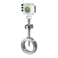
Digital output 41 / 42, 51 / 52 passive on distributed control
system
Transmitter
Distributed control system /
Memory programmable controller
1 Input 1
2 Input 2
X
Resistor for current limitation
I
Distributed control system
internal resistance
Figure 55: Digital output 41 / 42 on distributed control system (example)
The R
X
resistors limit the maximum current through the
optoelectronic coupler of the digital outputs in the transmitter.
The maximum permissible current is 25 mA. An R
X
value of
1000 Ω / 1 W is recommended at a voltage level of 24 V DC.
The input on the distributed control system is reduced from
24 V DC to 0 V DC (falling edge) with ‘1’ at the digital output.