SensyMaster FMT430, FMT450 THERMAL MASS FLOWMETER | OI/FMT430/450-EN REV. B 13
Electrical data
Overview
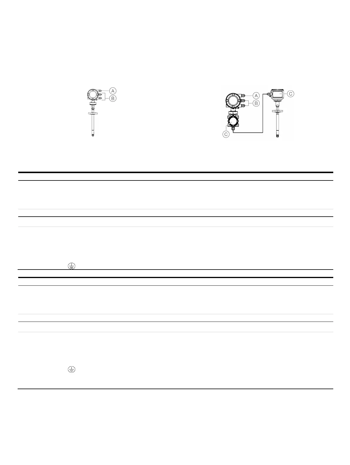
Integral mount design
Remote mount design
Power supply
Inputs / outputs, communication
Signal cable (remote mount design only)
Figure 1: Electrical connections overview
Activating the inputs and outputs
Power supply
Inputs / outputs, communication
Signal cable (remote mount design only)
Type of protection ATEX / IECEx:
Non-sparking ‘Ex ec’
Type of protection USA / Canada:
‘non IS’
Maximum 250 Vrms
Terminals: 1+, 2-, L, N,
Type of protection ATEX / IECEx:
non-sparking ‘Ex ec’
Type of protection USA / Canada:
Non-Incendive ‘NI’
Terminals: 31, 32, Uco, V1, V2, V3, V4, 41, 42, 51, 52
Type of protection ATEX / IECEx:
Non-sparking ‘Ex ec’
Type of protection USA / Canada:
Non-Incendive ‘NI’
Terminals: A, B, UFE, GRN
II 1/2 G & II 1 G & II 2 D
Activating the inputs and outputs
Power supply
Inputs / outputs, communication
Signal cable (remote mount design only)
Type of protection ATEX / IECEx:
Non-sparking ‘Ex eb’
Type of protection USA / Canada:
‘non IS’
Maximum 250 Vrms
Terminals: 1+, 2-, L, N,
Type of protection ATEX / IECEx:
non-sparking ‘Ex ec’
Type of protection USA / Canada:
Non-Incendive ‘NI’
When installing in ‘Ex ia’, suited intrinsically safe
isolation amplifiers must be used for the
connection.
• Terminals: 31, 32, Uco, V1, V2, V3, V4, 41, 42, 51, 52
Type of protection ATEX / IECEx:
Non-sparking ‘Ex eb’
Type of protection USA / Canada:
explosionproof ‘XP’
Terminals: A, B, UFE, GRN
Note
When installing in ‘Ex ia’ or ‘IS’ type of protection, the type of protection is determined by the type of electrical connection. The
information in Changing the type of protection on page 21 must be observed when changing the type of protection!