Installation and Commissioning Guide
Split Tri-Capacity
15
Installation and Commissioning Guide 500-700 Tri-Capacity Split Ducted
Doc. No.0525-098 Ver. 2 210330
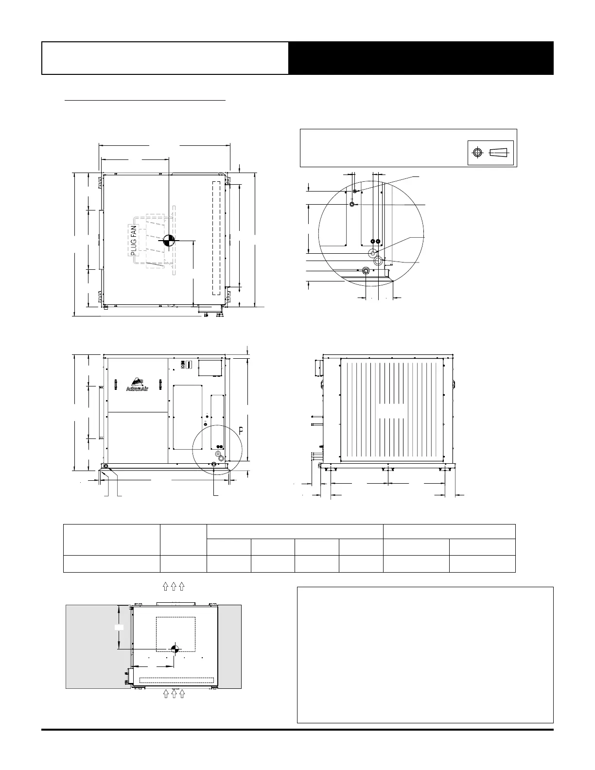
08. INDOOR DIMENSIONS
08.01. EVY500T Unit Dimension
XX
YY
1490
420
650
420
1590
O/A
1135
130
225
35
85
20
120
325
50
65
70
10080
LARGE GAS
Ø 28.6 (1-1/8")
DETAIL P
630
(MTG C-C DIST)
630
(MTG C-C DIST)
115
115
COIL
100
1450 O/A
350
580
350
1280
O/A
1130
1415
(MTG C-C DIST)
17.5
105
17.5
45
6 x Ø 15.0
MTG. HOLES
SAFETY TRAY DRAIN
Ø 25.4 (1")
BSP SOCKET
CONDENSATE DRAIN
Ø 25.4 (1")
BSP FEMALE THREAD
SMALL GAS
Ø 22.2 (7/8")
SMALL LIQ
Ø 9.52 (3/8")
LARGE LIQ
Ø 15.9 (5/8")
TOP VIEW
FRONT VIEW
SIDE VIEW
DETAIL P
DIMENSION H X W X D = 1280 X 1590 X 1450
SUPPLY DUCT H X W = 580 X 650
RETURN DUCT = 1130 X 1135
USE M12 BOLT FOR FEET MOUNTING
THIRD ANGLE
PROJECTION
Unit Model Number
Unit
Weight
Corner Weights(kg) Centre Of Gravity Position
A B C D XX YY
EVY500T 298 68 68 81 81 730 771
SERVICE ACCESS AREAS
TOP VIEW
D
A
YY
B
C
1000 mm
SERVICE
CLEARANCE
PLUG FAN
INDOOR COIL
HEIGHT CLEARANCE = 500
DUCT WORK
DUCT WORK
300 mm
SERVICE
CLEARANCE
ActronAir is constantly seeking ways to improve the design of it's products, therefore specifications are subject to change without notice. Please check prior to purchase. EVY470T-6Q1 100325
XX
NOTES:
1. Do not scale drawing. All dimensions are in mm unless specified. Refer
to corresponding unit dimensional drawing for mounting hole details.
2. Service Access Areas and Spaces for Airflow Clearances given are
suggested minimum based on the condition that the spaces around
the units are free from any obstructions and a walkway passage of
1000mm between the units or between the unit and the outside
perimeter is available.
3. Minimum service access areas and spaces for airflow clearances are
responsibilities of the installer, ActronAir will not be held liable for any
extra charges incurred due to lack of access and space for airflow.