36
Installation and Commissioning Guide 500-700 Tri-Capacity Split Ducted
Doc. No.0525-098 Ver. 2 210330
Installation and Commissioning Guide
Split Tri-Capacity
15. ELECTRICAL
NOTES
• All electrical work must be carried out by a qualified technician.
• Make sure all wiring is in accordance with local wiring rules.
• Wiring connections should be made in accordance with the provided wiring diagram.
• The unit wiring diagram is located in the Access Panel - Electrical.
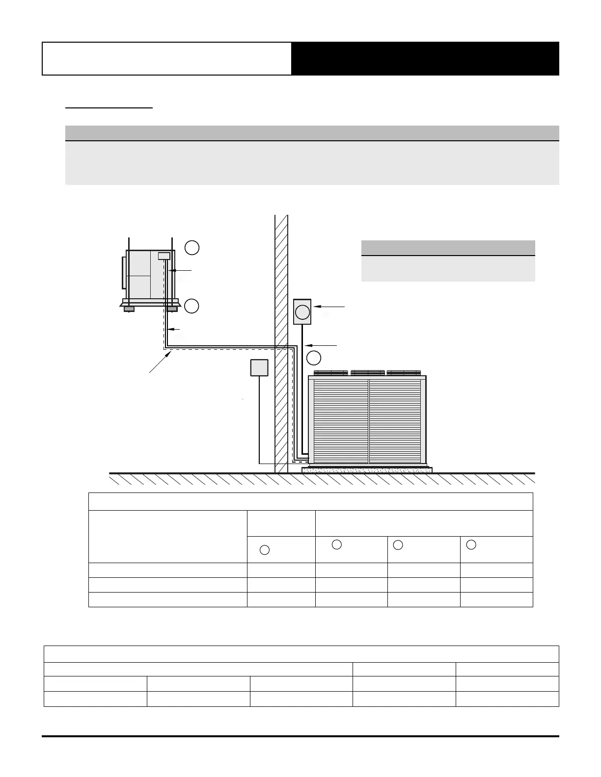
15.01. Split Unit Electrical Connection
NOTE
Please see Maximum Cable Lengths on next
page for cable specifications.
INTER-CONNECTING
CONTROLLER CABLE
OUTDOOR - CIB
WALL
CONTROL
(Optional)
CIRCUIT BREAKER
(Field Supplied by Installer)
SUB-MAIN
TO UNIT
(Field Supplied by Installer)
OUTDOOR
UNIT
INDOOR
UNIT
A
B
INTER-CONNECTING
CONTROL POWER CABLE
OUTDOOR - INDOOR
C
INTER-CONNECTING
FAN POWER CABLE
OUTDOOR - INDOOR
D
D
POWER CIRCUIT BREAKER SIZE AND CABLE SIZE
Model
Circuit
Breaker Size
Cable Size * (mm
2
)
Amps
Main
(4 Core +E)
O.D. to I.D.
(2 Core + E)
O.D. to I.D.
(3 Core + E)
CAY500T EVY500T ELY500T
50.0 10.0 1.0 1.5
CAY620T EVY620T ELY620T
63.0 16.0 1.0 1.5
CAY700T EVY700T ELY700T
80.0 25.0 1.0 1.5
* Suggested Minimum Cable Size should be used as a guide only, refer to AS/NZS 3000 “Australian / New Zealand Wiring Rules” for more details.
B
A
C
WIRING DIAGRAM MATRIX SPLIT DUCTED INDOOR STANDARD MODELS
Model Wiring Diagram DESCRIPTION
EVY500T EVY620T EVY700T 0515-8804 STANDARD PROFILE
ELY500T ELY620T ELY700T 0515-8801 LOW PROFILE