42
Installation and Commissioning Guide 500-700 Tri-Capacity Split Ducted
Doc. No.0525-098 Ver. 2 210330
Installation and Commissioning Guide
Split Tri-Capacity
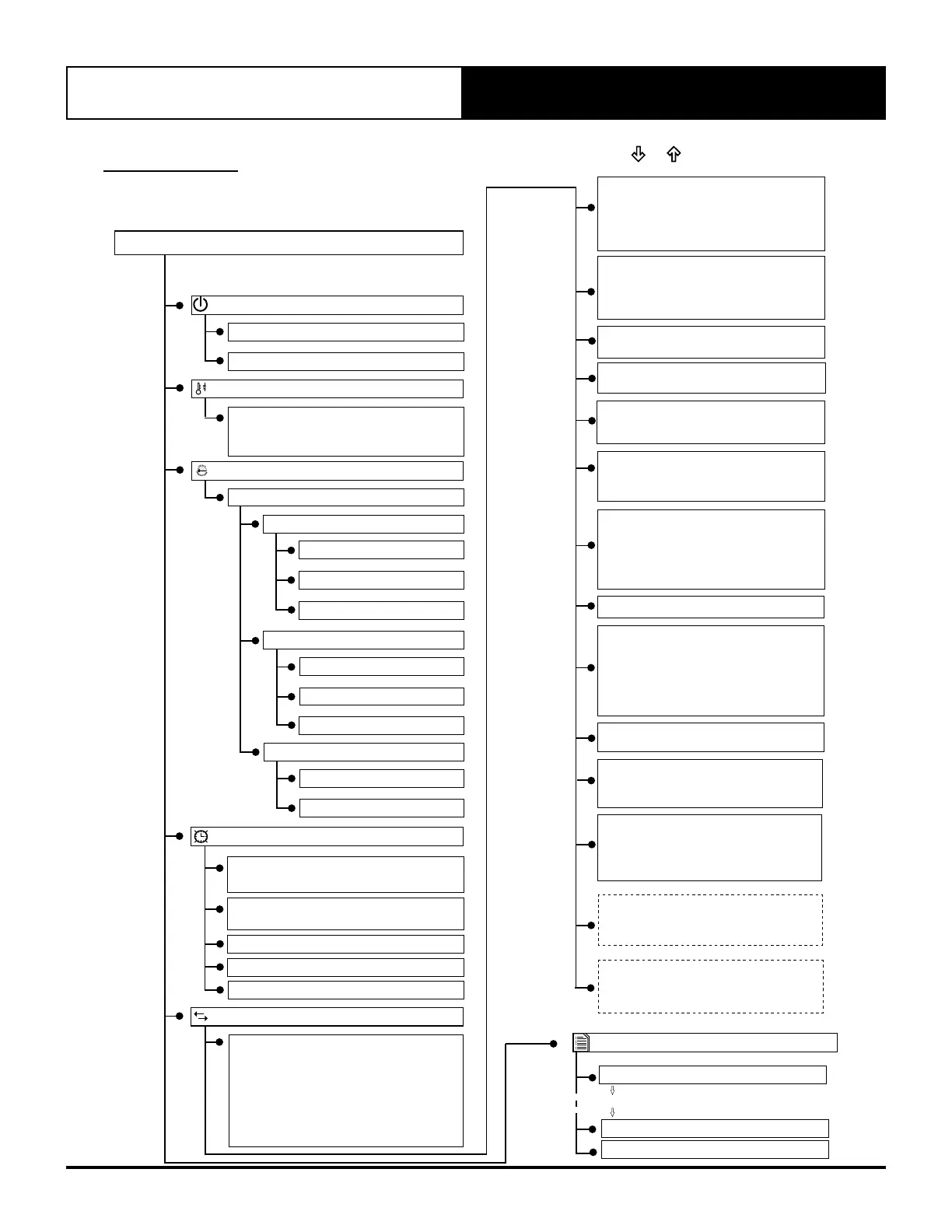
17. MENU TREE
17.01. Main / Status Menu
Main Menu
Log 100 - Recent Alarm
F. Alarm History
Log 1 - Recent Alarm
Reset Alarm Log
UP TO
E9. Supply Fan Speed Status
Condenser Fan Speed Status
Economy Cycle Output Status
E10-E12. Ref. Circuit (1,2 and 3)
Compressor Status
Reversing Valve Status
Cond Fan Low Spd Status
Cond Fan Hi Speed Status
E5. Demand Management 1
Demand Management 2
Demand Management 3
A/Hours Input Status
E6. HP Status
LP Status
A. On / Off Unit
A1. Turn Unit - ON / OFF / FAN ONLY
A2. Display Backlight - Auto / ON / OFF
B. Setpoint
B1. Setpoint
Temp. Setback - Enable / Disable
Cooling Limit/ Heating Limit
Note: To scroll Up or Down from existing
menu, press or button.
D. Clock / Scheduler
D1. Set the Day, Date, Time,
Scheduler - Enable / Disable
D7. After Hours Duration Setting
D8-D19. Special Days Setting
D3-D6. 7 Days Schedule Start / End
D2. Day Light Saving Time
Enable / Disable
Auto Change Over
C1. Operation Mode
Mode
Fan Speed (Optional 3-Speed)
Fan Mode
Cool Only
Low
Continuous
High
Heat Only
Medium
Auto Cycle
C. Mode of Operation
50+
o
C
10
o
C
-
E. Status
E1-E3. Disch Temp (Crt 1,2 and 3)
OD Coil Temp (Crt 1 and 2)
Room Temp
CO
2
Sensor
Outside Air Temp
External ID Fan Speed Status
External Capacity Status
E13. Output 8: On/Off
E14. Indoor Fan Board
Indoor Fan 1: On/Off
Indoor Fan 2 On/Off
Supply Fan 1: PWM
Supply Fan 2: PWM
Aux Relay ON/OFF
E15. Indoor Fan Board
Anti-freeze Level 1, 2, 3 On/Off
E26. Indoor Fan Board
Current Mode:
Unit Select:
E27. Minimum Outside Position
Internal/BMS/CO
2
Sensor
Economy Output (%)
Damper Command (V)
E8. Digital Inputs
Indoor Fan Board
Fan Fault, Dip Switches
E7. Stage 1, 2 and 3 Call
Heat Mode Call
E4. Indoor coil temp
Room Temp
Indoor 0-10V in
Indoor Pot val.
Indoor Current
E28. RS485 Outside Probe*
Temperature/Humidity
Dew Point/Enthalpy
E29. RS485 Room Probe*
Temperature/Humidity
Dew Point/Enthalpy
*Available when enabled via Service Menu.