80
Installation and Commissioning Guide 500-700 Tri-Capacity Split Ducted
Doc. No.0525-098 Ver. 2 210330
Installation and Commissioning Guide
Split Tri-Capacity
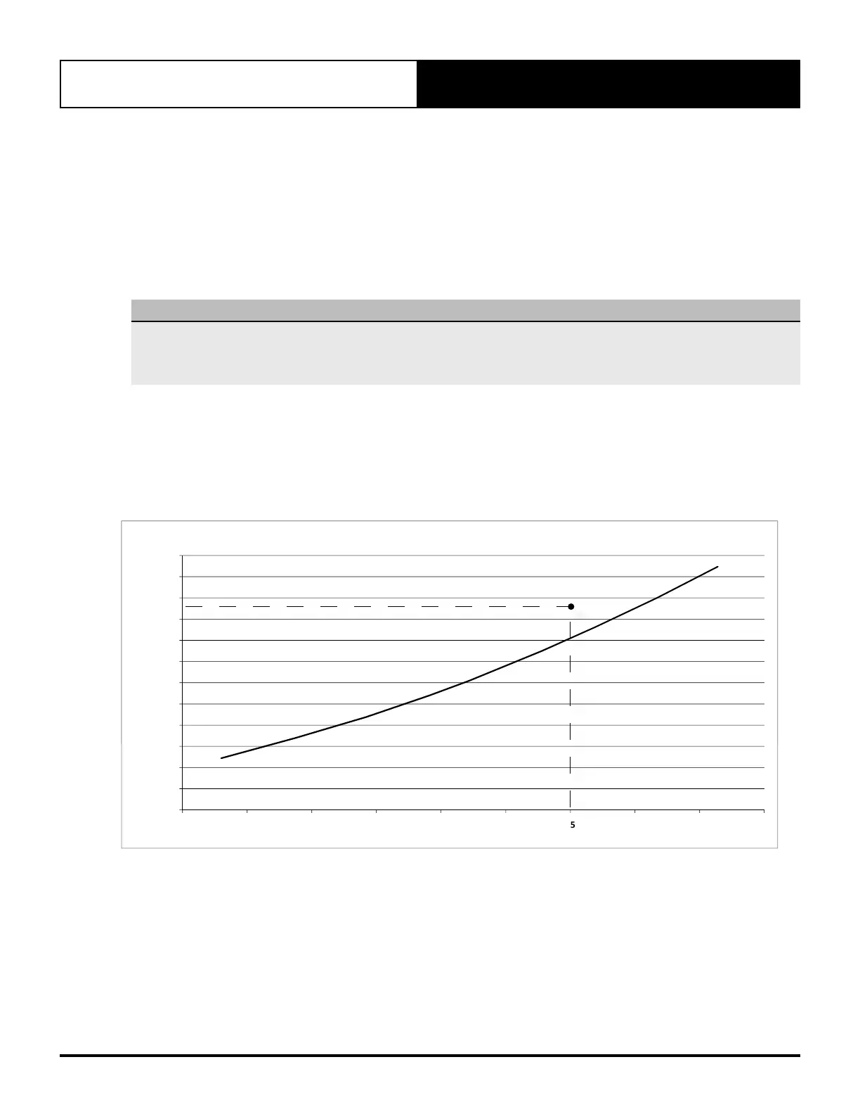
28.02. Charging Method 2: Cooling Charging Curve
1. Start and run the unit in cool mode, ensuring that both circuit compressors are in 100% operation and systems
stabilised for 20 minutes, record discharge pressure and liquid line temperature.
2. Plot the data in the cooling charging curve below.
3. If the plotted data point falls above the charging curve, it is necessary to remove refrigerant.
4. If the plotted data point falls below the charging curve, it is necessary to add refrigerant.
5. Repeat Steps 1 -4 until the plotted data point falls along the curve.
NOTE
• Accurate pressure and temperature measuring tools should be used to achieve satisfactory results. The sensors
of thermocouple must be in good contact with the area being measured and must be insulated in order to obtain
correct reading.
• Dirty filters, blocked coils etc. can cause pressure readings obtained to be incorrect.
EXAMPLE:
Discharge Pressure = 3350 kPa
Liquid Line = 45
o
C
Action: Remove refrigerant charge from the system.
2000
2250
2500
2750
3000
3250
3500
3750
4000
ischargePressure,kPag
CoolingChargingCurve
1000
1250
1500
1750
2000
2250
2500
2750
3000
3250
3500
3750
4000
15 20 25 30 35 40 45 50 55 60
DischargePressure,kPag
LiquidLineTemperature,
o
C
CoolingChargingCurve
Remove charge
Add charge