40
Installation and Commissioning Guide 500-700 Tri-Capacity Split Ducted
Doc. No.0525-098 Ver. 2 210330
Installation and Commissioning Guide
Split Tri-Capacity
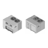
15.05. Demand Response Management
Secure the cables firmly
using the cable ties and
clamp provided in the
panel.
TERMINALS
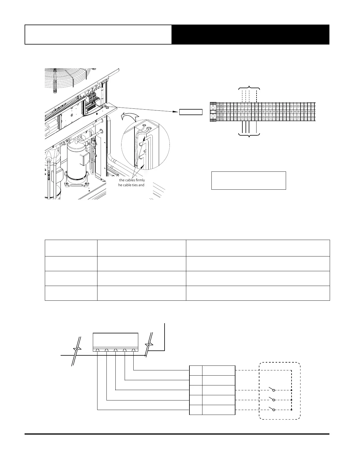
Refer to diagram below for
details of DRM connections.
7 8
9
11
DRM
Control Inputs
To Outdoor
Control
1. Thread and Route the DRM input cables into the Unit
• Thread and Route cables as per previous wiring installation procedures.
2. Connect cables into the terminals
• Connect cables as shown above and as per wiring diagram provided with the unit.
Demand
Management Mode
Description Of Mode Operating Mode
DRM1 Compressor Off
Compressors ONLY will cycle OFF and remain off for the entire
Demand Response Event.
DRM2
Maximum 50% power use mode.
(Over each 1/2 hour period)
Compressor 1 operation only for the total
Demand Response event.
DRM3
Maximum 75% power use mode.
(Over each 1/2 hour period)
Compressor 2 operation only for the total
Demand Response event.
J7
DEMAND RESPONSE
ENABLING DEVICE DRED
AS4755 COMPLIANT DEVICE
(OPTIONAL)
TERMINALS
OUTDOOR CONTROL
11
COMMON (GND)
10
REMOTE ON/OFF
9
DRM 3
8
DRM 2
7
DRM 1
DRM 3
DRM 2
DRM 1
DI1
DI2
DI3
DI4
GND
DEMAND RESPONSE MANAGEMENT CONNECTION DIAGRAM