Installation and Commissioning Guide
Split Tri-Capacity
43
Installation and Commissioning Guide 500-700 Tri-Capacity Split Ducted
Doc. No.0525-098 Ver. 2 210330
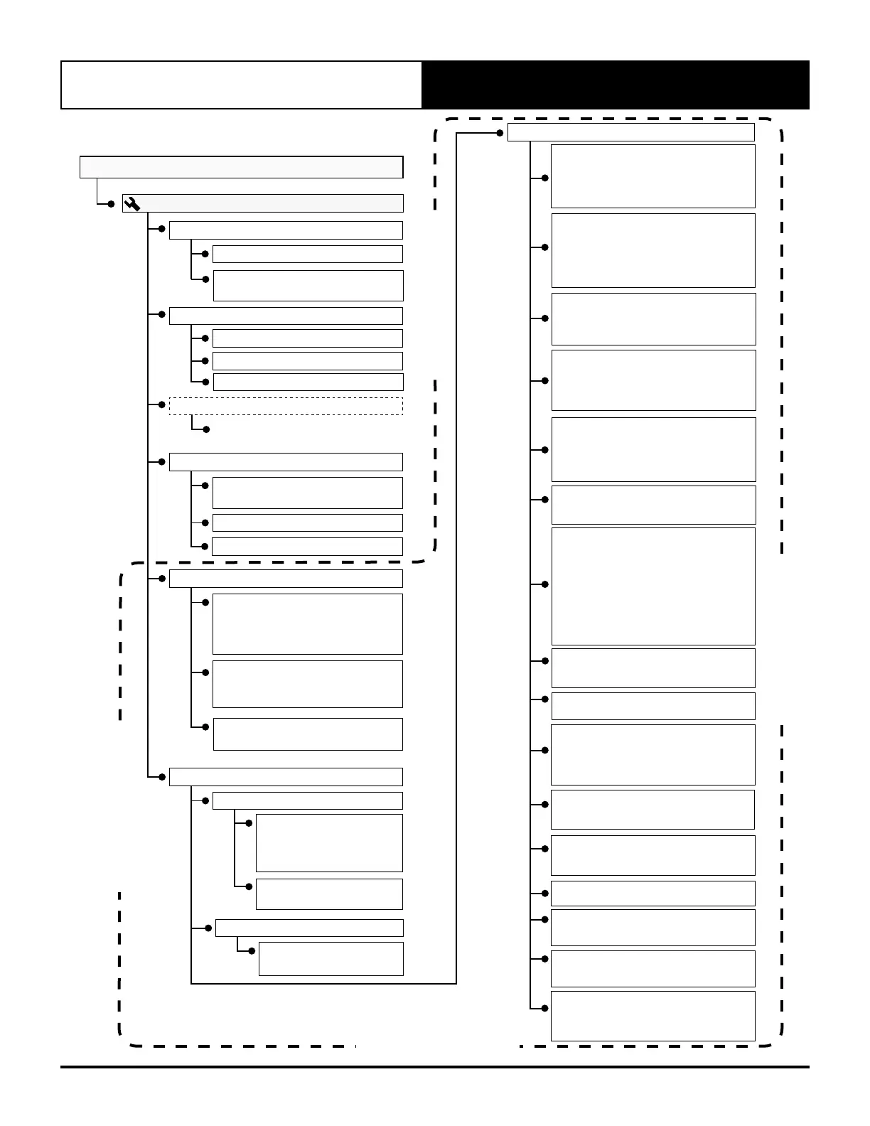
17.02. Service Menu
(PASSWORD PROTECTED)
(PASSWORD PROTECTED)
(PASSWORD PROTECTED)
(PASSWORD PROTECTED)
Ga1. Enter Language Change
Gfc17(OD) - Gfc18(ID). Alarms Disable
Rtn Air Sensor Y/N
Ga. Change Language
Gb. Information
Gb1. Software Information
Gb2. Hardware Information
Gd2. Setpoint logging / Reset
Gd3. Supply Fan logging / Reset
Main Menu
G. Service
Gc. Board Switch
Gd1. Indoor Fan Hr Run / Filter hr
Comp. Hr Run (Crt 1,2 and 3)
Ge1. BMS Configuration
Address
Protocol
Speed (baud rate)
Ge2. Enable BMS to Turn the
Unit On/Off
On loss of Comms On/Off
Gfa1. Indoor Filter
Filter Fault Rly Y/N
Indoor Fan
Compressor
Ge3. Enable DIN4 to Turn the
Unit On/Off
Gd. Working Log
Gfa. Working Hour set
Gf. Service Setting
Gfc. Thermoregulation
Ge. Communicate Config
Gfc1. Room Temp. Setpoint
Dead Band
Cooling Prop band
Heating Prop band
Integral time
Gfc2. Room Temp use ID sensor
After Hours (SW & Temp./SW Only)
Probe weight value
Room Temperature
Wall Control Temp.
Control Value
Gfc6. Room Setpoint limit
Minimum / Maximum by User
User Setpoint Lock/Unlock
User mode sel. Lock/Unlock
Mode Lock Timer Setting
Gfc4. Supply Fan Speed
Min/ Med/ Max
Supply Fan Temp.
Min / Max
Gfc5. Supply fan Gen. 3/Continuous : Y/N
Cycle on de-ice Setting : Y/N
Number of Fan Speed Setting
Supply Fan Run On Setting
Heat Start Delay Setting
Gfc13. Type of Fans Fitted
Supply / Outdoor
Outdoor Init Speed (%) & OF1/OF23
Econ. cycle fitted: Y/N
Econ. cycle type: Mod:On/Off
Gfc7. Enable Night Mode by Sched.
Start/Stop Finish Time
Max Cond fan spd & cct 2 max spd
Gfc12. Unit Configuration
Series, Model & Variations
Gfc11. Unit Mode Configuration
Supply Fan Control Setting
Select Wall Control
Gfa2. Reset ID Fan / Filter
/ Comp.
Unit Address
Switch to Unit
G. Probe Adjustment
G1. Room Temp. Calibration
Multi Input Calibration
Ga2. Disable Language Mask at
Startup: Yes/No
Gb4. Fan Board Information
Gfc19. Damper Scaling
Command Start / End
Output Start / End
Gfc31. CO
2
Control Start / End
Alarm Output: enable/Disable
Sensor Fault
Gfc8. Sensor present:
Multi Input 1/2: Y/N
Supply Air Temp
CO
2
Sensor
Economy Enable
Night Mode Enable
0-10V Stage Cont
0-10V In Fan Spd
View Only Input
Phase Fail Relay
Gfc14. Default Initialisation
Erase User settings and
install global default value Y/N
Gfc15. Room Temp / Humidity
Gfc16. Outside Temp / Humidity
Sensor fitted/Use this temp sensor
Gfc32. Compressors
1st Stage Start / Stop
2nd Stage Start / Stop
3rd Stage Start / Stop