Installation and Commissioning Guide
Split Tri-Capacity
81
Installation and Commissioning Guide 500-700 Tri-Capacity Split Ducted
Doc. No.0525-098 Ver. 2 210330
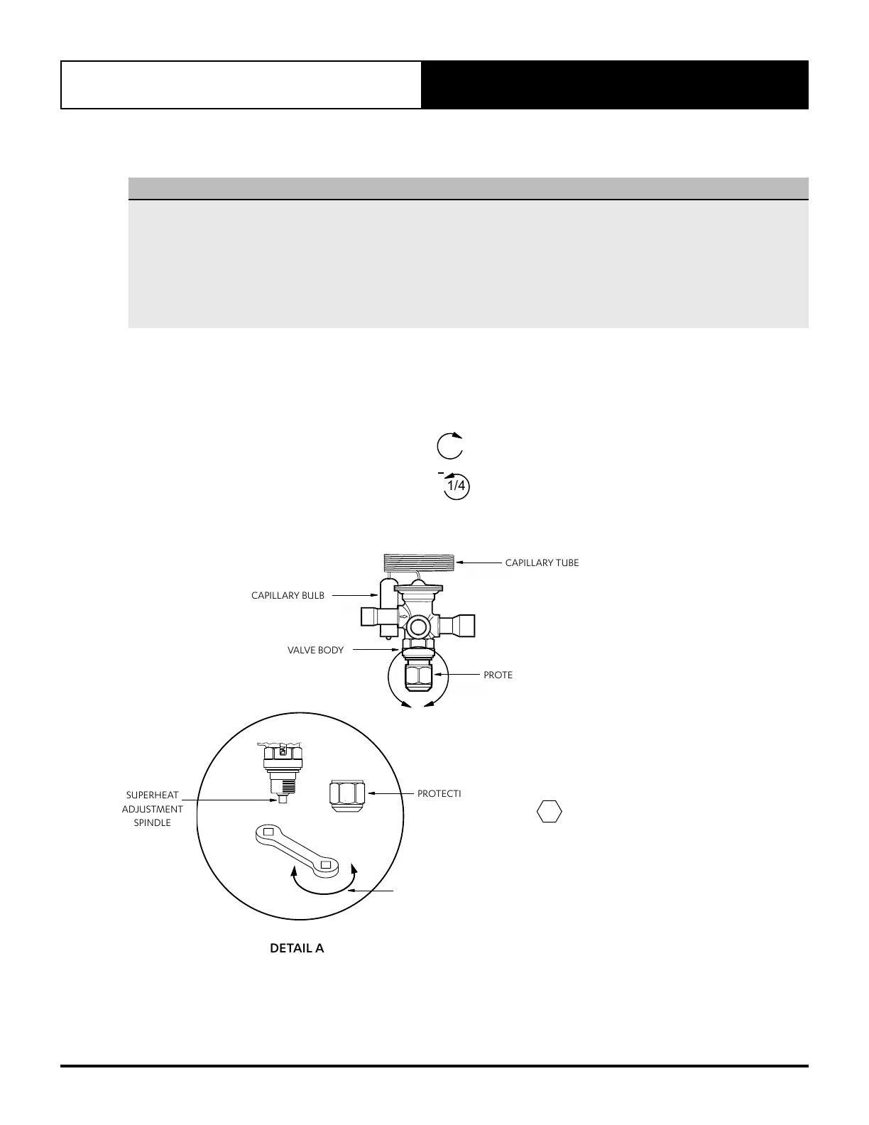
28.03. Thermal Expansion Valve (TXV) Adjustment
CAUTION
• Allow the systems to stabilise for 20 minutes before adjusting the thermal expansion valve (TXV) in order to ensure
correct subcooling and superheat conditions. Turn Superheat Adjustment spindle 1/4 turn at a time, stabilising the
systems in between adjustment, check condition, adjust again if necessary, until correct subcooling and superheat
conditions are attained.
• A total of 4 Thermal Expansion Valves are provided for the Outdoor and Indoor unit combination (2 per unit).
Fo r example:
Outdoor Unit = 1 x TXV for Small Compressor (Crt. 1) + 1 x TXV for Large Compressor (Crt. 2)
Indoor Unit = 1 x TXV for Small Compressor (Crt. 1) + 1 x TXV for Large Compressor (Crt. 2)
Subcooling Adjustment
(Refer Subcooling Adjustment to Refrigerant Charging Section).
Superheat Adjustment
If superheat is lower than 2k = turn Adjustment Spindle
1/4
+
, stabilise system for 20 minutes, adjust if required.
If superheat is higher than 8k = turn Adjustment Spindle
1/4
, stabilise system for 20 minutes, adjust if required.
See Diagram Below:
© Danfoss A/S (AC-BNM/mr), 01 - 2008 DKRCC.PI.AN0.A4.02 / 520H2448 1
Instructions
TR 6
067R9508
067R9508
PS = 42 bar /( MWP = 610 psig)
p
test
= max. 47 bar (680 psig)
Reverse: B→A
Normal: A→B
Flow direction:
Q
nom.
A → B [kW] = 100%
Q
nom.
B → A [kW] = 80%
Adjustable setting
Fixed setting
CAPILLARY BULB
VALVE BODY
CAPILLARY TUBE
PROTECTIVE CAP
A
14 TURN AT A TIME
SUPERHEAT ADJUSTMENT
2 DKRCC.PI.AN0.A4.02 / 520H2448 © Danfoss A/S (AC-BNM/mr), 01 - 2008
SS = 2°C (3.6°F) or according
to customer speci cation
Number of turns
from SS to
tight spring
Number of turns
from SS to
loose spring
R22 +7.25 –4.25
R410A +9.5 –2
DETAIL A
SUPERHEAT
ADJUSTMENT
SPINDLE
PROTECTIVE CAP
- 1/4
Turn
+ 1/4
Turn
= 19MM 34”
T = 10NM 7 FTLBF