Installation and Commissioning Guide
Split Tri-Capacity
33
Installation and Commissioning Guide 500-700 Tri-Capacity Split Ducted
Doc. No.0525-098 Ver. 2 210330
REFRIGERATION PIPING
Outdoor Model
Indoor Model
CAY500T
EVY500T
ELY500T
CAY620T CAY700T
EVY620T
ELY620T
EVY700T
ELY700T
Maximum Equiv. Pipe Length Range metres 0 - 75 0 - 75 0 - 75
Maximum Vertical Height Difference* metres 20 20 20
Field Pipe Sizing
Liquid Circuit #1 mm (inch) 9.5 (3/8) 12.7 (1/2) 12.7 (1/2)
Gas Circuit #1 mm (inch) 22.2 (7/8) 25.4 (1) 25.4 (1)
Liquid Circuit #2 mm (inch) 15.9 (5/8) 15.9 (5/8) 15.9 (5/8)
Gas Circuit #2 mm (inch) 28.6 (1-1/8) 28.6 (1-1/8) 28.6 (1-1/8)
Outdoor and Indoor Unit Connection (SWAGED PIPE)
Liquid Circuit #1 mm (inch) 9.5 (3/8) 12.7 (1/2) 12.7 (1/2)
Gas Circuit #1 mm (inch) 22.2 (7/8) 25.4 (1) 25.4 (1)
Liquid Circuit #2 mm (inch) 15.9 (5/8) 15.9 (5/8) 15.9 (5/8)
Gas Circuit #2 mm (inch) 28.6 (1/1/8) 28.6 (1-1/8) 28.6 (1-1/8)
NOTE
*Included in maximum field pipe length.
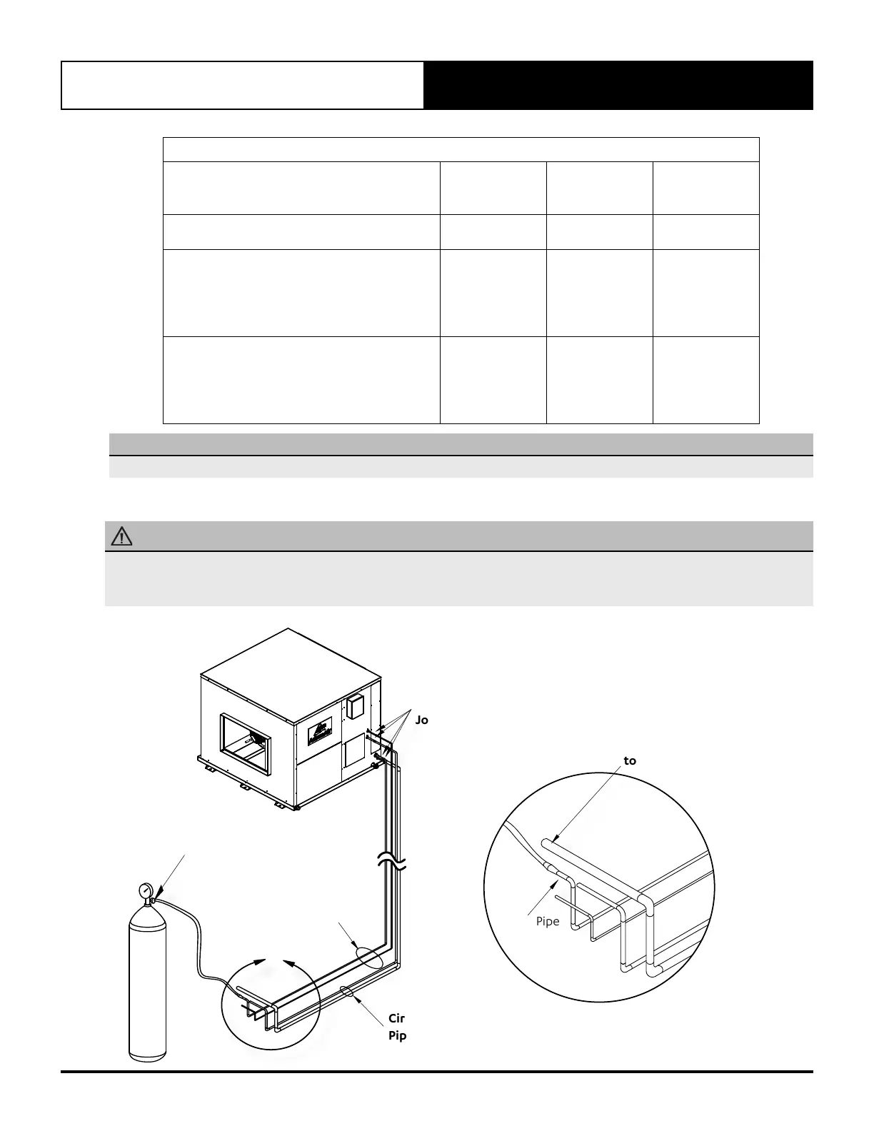
14.03. Pipe Installation
PRECAUTION
Brazed joints should only be made while purging Nitrogen through the system.
Failure to do so will cause carbon deposit to be left on the internal pipe surface, that in turn can cause system failure and void
of warranty.
N
I
T
R
O
G
E
N
Circuit 1
Piping
Circuit 2
Piping
Nitro
Regulator
Set to 2 L/s
A
Braze
Joints
Rubber bung
into suction pipe
to create seal
Open Pipe
DETAIL A