Installation and Commissioning Guide
Split Tri-Capacity
63
Installation and Commissioning Guide 500-700 Tri-Capacity Split Ducted
Doc. No.0525-098 Ver. 2 210330
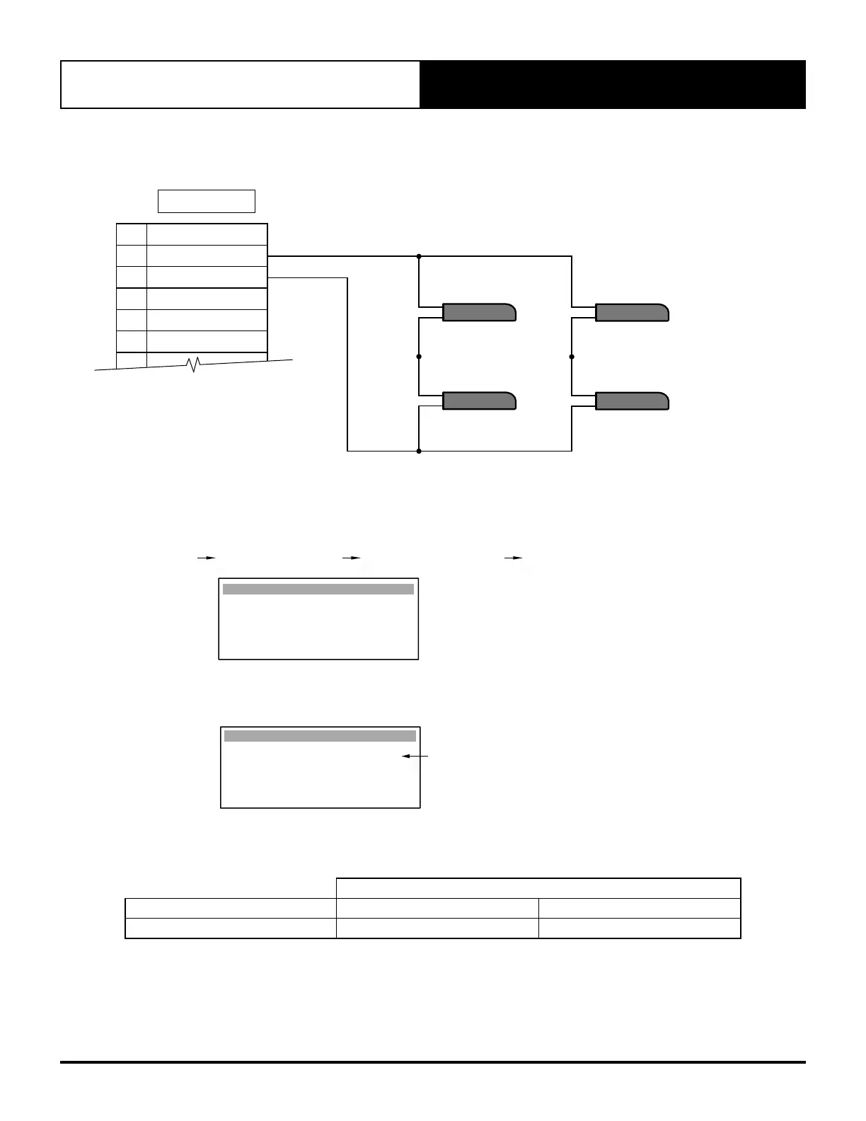
23.02. Averaging Four Room Air Temperature Sensors (Optional)
Additional sensors may be purchased separately from ActronAir.
ROOM TEMP
10k NTC SENSOR 3
ROOM TEMP
10k NTC SENSOR 4
ROOM TEMP
10k NTC SENSOR 1
ROOM TEMP
10k NTC SENSOR 2
TERMINALS
18 AFTER HOURS
17 RTN AIR SENSOR
16
RTN AIR SENSOR (GND)
15 MULTI INPUT 2
14 COMMON (GND)
13 MULTI INPUT 1
12
23.03. Room Temperature Sensor Adjustment Instructions
To calibrate the Room Air Temperature sensor, follow the service menu steps:
G. Service Gf. Service settings G. Probe adjustment G1. Calibration
Calibration Gfb1
Room Temp cal : 0.0
o
C
Example:
If the actual measured room temperature is 2.0
o
C higher than control interface reading, adjust the offset to -2.0
o
C.
Adjustable offset range is from -9.9
o
C to +9.9
o
C.
Room Temp cal : +2.0
o
C
Calibration Gfb1
Probe Adjustment Display
Enter room air temp. offset here
23.04. Specifications - Sensor Lead Wire
Distance
Item up to 50m up to 100m
NTC (Sensor Wire) * 0.5mm
2
1.0mm
2
* For compliance with EMC requirements, connect the screen wire to Terminal 22 on the Outdoor Terminal Strip.
Use only the provided ActronAir duct bead sensor or the optional wall sensor.
Use of Third Party sensors are done at the contractors' risks and ActronAir accepts no responsibility for performance
or sensing issues.