Installation and Commissioning Guide
Split Tri-Capacity
53
Installation and Commissioning Guide 500-700 Tri-Capacity Split Ducted
Doc. No.0525-098 Ver. 2 210330
18.03.01. Compressors 24VAC External Control Mode
Compressors are configured through a 24VAC input from the external control. This is the DEFAULT
compressor configuration. If this is the compressor external input requirement, no control interface
configuration is required. Refer to the wiring diagram for wiring connection.
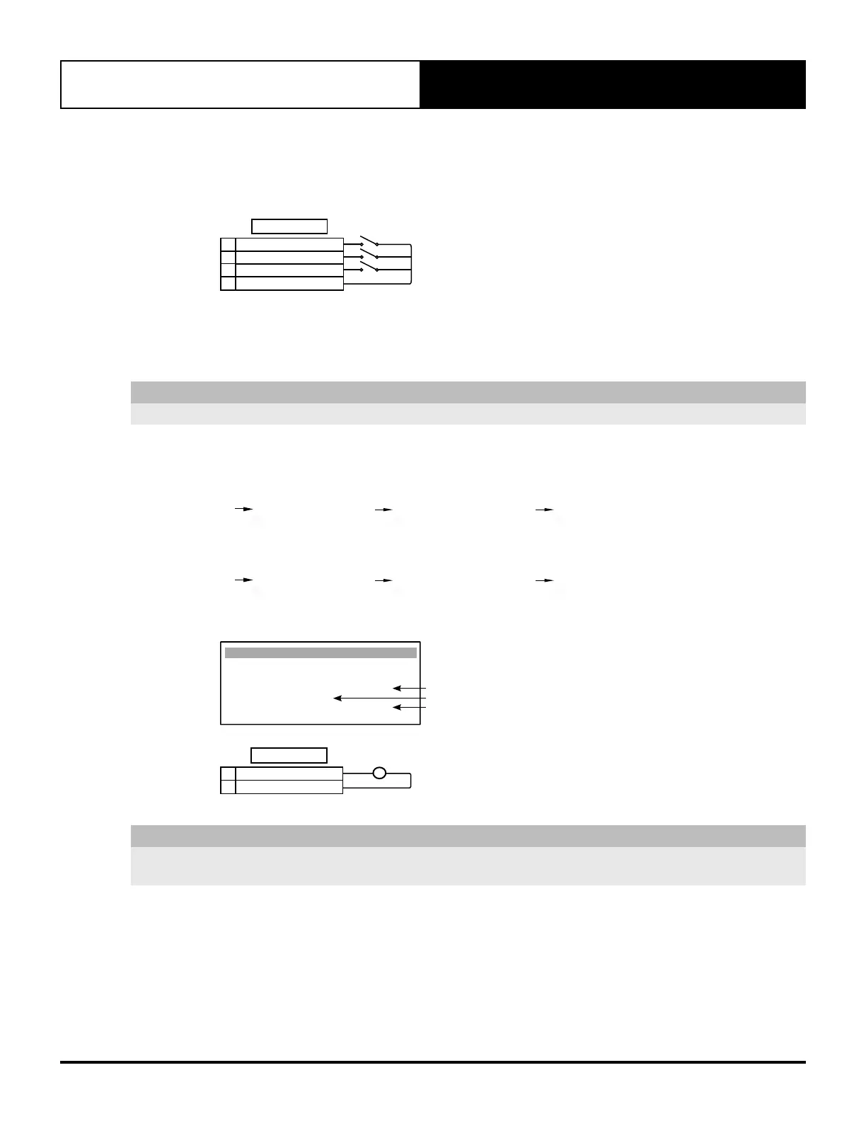
STAGE 3 (24VAC IN)
STAGE 2 (24VAC IN)
TERMINALS
STAGE 1 (24VAC IN)
24VAC OUT
4
3
2
1
18.03.02. Compressors 0-10VDC External Control Mode
Compressors can be controlled through a 0-10VDC input from the external control.
NOTE
If a 0-10V input is required the multi-input must be changed as shown per procedure.
Compressors Configuration Procedure for 0-10VDC External Control Mode:
Assign a Multi Input to the Compressors via S. Configuration screen Gfc8:
G. Service Gf. Service settings Gfc. Thermoregulation Gfc8. S. Configuration
Ensure that the Multi Input assigned to the Compressors is set to
*
0-10v STAGE CONT.
*
and the
Probe type: is set to 0 - 10V
G. Service Gf. Service settings Gfc. Thermoregulation Gfc8. S. Configuration
Example shown below is for Compressors with external input assigned to Multi Input 2:
S. Conguration Gfc8
Sensor present :
Multi Input 1: NO
Multi Input 2: YES
*0 - 10v STAGE CONT. *
Probe type: 0 - 10V
*0 - 10v STAGE CONT. *
0 - 10V
YES
V
0-10V
DC
TERMINALS
MULTI INPUT 215
COMMON (GND)14
NOTE
For W- 3 Phase Sequence Relay Option, Multi Input 2 (U12) is already used for 24VAC supply. Multi Input 1 (U11) must be
used instead.