Installation and Commissioning Guide
Split Tri-Capacity
71
Installation and Commissioning Guide 500-700 Tri-Capacity Split Ducted
Doc. No.0525-098 Ver. 2 210330
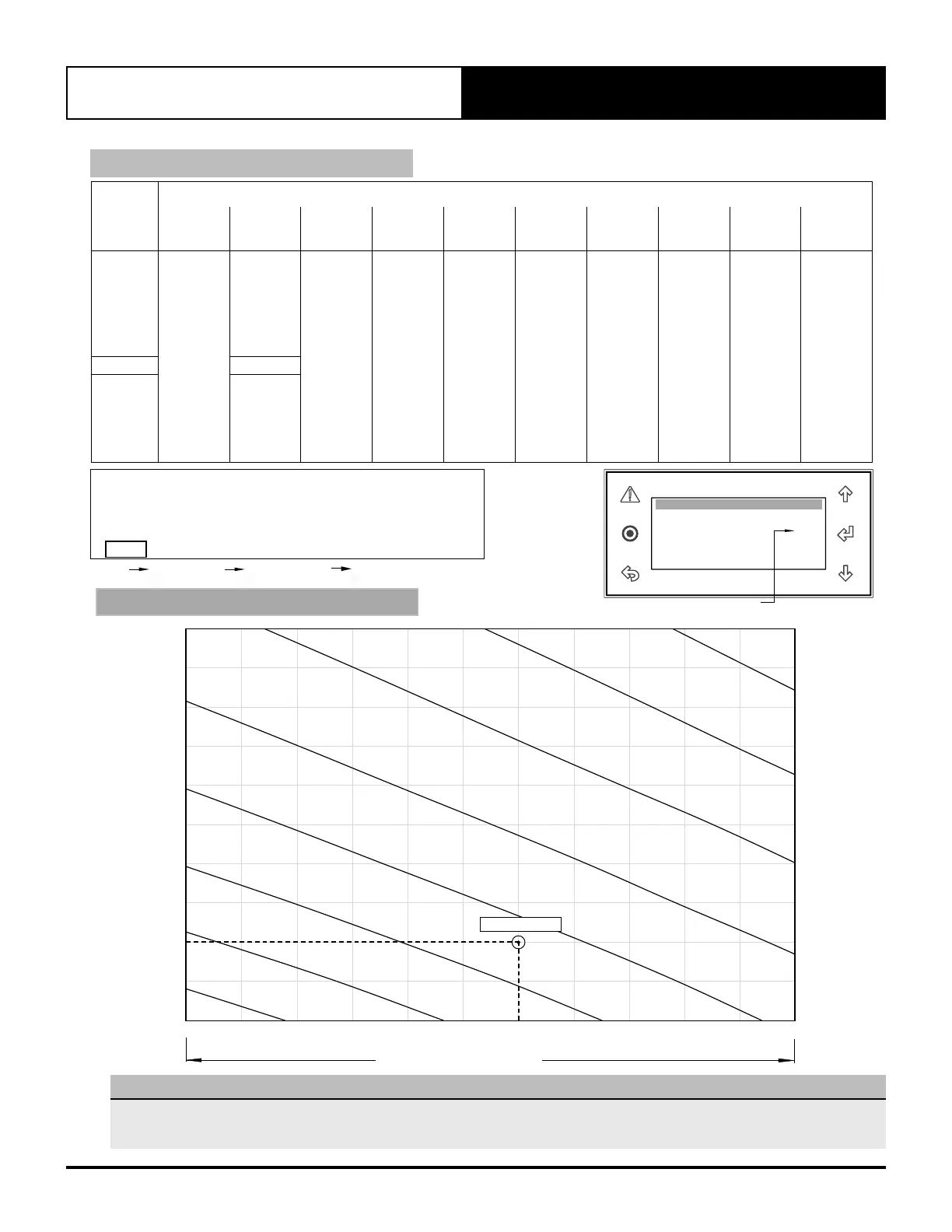
AIRFLOW (l/s)
Nominal Airflow = 2600 l/s
APPLICATION RANGE
0
50
100
150
200
250
300
350
400
450
500
2000 2100 2200 2300 2400 2500 2600 2700 2800 2900 3000 3100
Static Pressure (Pa)
Volume Flow (l/s)
Static Pressure Vs Volume Flow
EXISTIN G
40%
45%
50%
NEW
30%
35%
40%
45%
50%
55%
60%
65%
70%
75%
80%
85%
90%
95%
99%
2400 2700 30002000 2500 2800 31002200 2600 29002100 2300
50
100
300
200
400
500
150
350
250
450
0
53.2% Speed
70% Speed
65% Speed
60% Speed
55% Speed
45% Speed
40% Speed
50% Speed
CAY500T / ELY500T
FAN PERFORMANCE DATA
Airflow
(l/s)
External Static Pressure (Pa)
50 100 150 200 250 300 350 400 450 500
%
Spd.
W
%
Spd.
W
%
Spd.
W
%
Spd.
W
%
Spd.
W
%
Spd.
W
%
Spd.
W
%
Spd.
W
%
Spd.
W
%
Spd.
W
2000 40.7 585.6 44.2 748.3 47.4 918.7 50.2 1082.2 52.8 1253.5 55.2 1411.5 5 7.6 1593.2 59.7 1758.0 61.7 1912.2 63.7 2032.5
2100 42.3 644.0 45.7 814.0 48.7 1005.3 51.6 1180.5 54.1 1337.5 56.5 1511.0 58.8 1687.8 60.9 1851.4 62.8 2004.3 64.6 2137.3
2200 43.9 711.2 4 7. 2 888.3 50.1 1068.0 5 2.9 1251.3 55.4 1412.9 5 7. 8 1612.3 60.0 1784.8 62.0 1969.3 63.9 2141.5 65.8 2242.0
2300 45.5 775.0 48.7 971.6 51.6 1156.3 54.3 1330.6 56.7 1520.7 59.0 1717.9 61.2 1902.2 63.1 2078.1 65.0 2246.6 67.0 224 7. 5
2400 47.1 845.5 50.2 1037.1 53.0 1228.7 55.6 1415.7 58.0 1614.3 60.3 1806.8 62.3 1999.2 64.3 2182.5 66.3 2368.1 68.3 2366.0
2500
48.7 913.2
51.7 1125.9
54.4 1311.9 57.0 1513.8 59.3 1712.0 61.5 1912.6 63.5 2104.3 65.5 2295.2 67. 5 2491.5 69. 5 2489.5
2600 50.4 1008.4 53.2 1208.0 55.9 1402.1 58.3 1611.5 60.6 1813.7 62.7 2020.6 64.7 2215.1 66.8 2432.5 68.8 2644.4 70.9 2766.3
2700
52.0 1027.4
54.7 1293.7
57.3 1504.8 59.7 1708.5 61.9 1919.9 64.0 2127.5 66.1 2 349.1 68.1 2567.8 70.1 2782.5 72.4 2780.1
2800 53.6 1180.0 56.2 1379.2 58.8 1603.1 61.0 1813.1 63.1 2027.0 65.2 2241.2 67.4 2481.7 69. 5 2702.0 71.7 2940.5 73.9 2938.2
2900 55.2 1256.5 57.7 1480.9 60.2 1704.5 62.3 1924.2 64.4 2135.9 66.6 2376.8 68.8 2617.4 70.9 2847.9 73.2 3089.0 75.5 3280.0
3000 56.8 1361.2 59.2 1584.2 61.6 1819.6 63.6 2036.8 65.7 2261.8 68.0 2511.6 70.2 2754.6 72.5 2999.4 74.7 3236.3 77. 7 3347.5
3100 58.3 1467.4 60.7 1692.9 63.0 1933.0 65.0 2147.6 67.3 2403.0 69.4 2646.9 71.7 2901.8 74.1 3156.9 76.1 3418.0 79.0 3415.0
Thermoregulat. Gfc4
Supply Fan
Minimum Temp. 5.0
o
C
Maximum Temp. 50.0
o
C
Minimum speed: 40.7%
Medium speed: 53.2%
Maximum speed: 79.0%
Supply Fan Temp.
Set Fan Speed
*Service Service Settings Thermoregulation Thermoregulat. Gfc4
NOTES:
% Speed = Indoor Fan Speed Control Setting, in percent
(Value is set on the Control Interface via Service Menu *).
W = Indoor Fan Power, Watts
- Data in the box indicates Factory Default Setting.
INDOOR UNIT FAN CURVE
EXTERNAL STATIC
PRESSURE (Pa)
NOTE
Fan Performance Data and Fan Curve shown is at dry coil and with no air filters installed. Consider external static pressure drop specific to your design
requirements. Airflow should be reduce with respect to the moisture content in the air. Please review filter manufacturer for application. 2.5 m/s face
velocity point will occur at 3515 l/s.
75% Speed