EasyManua.ls Logo

Adtech ADTECH4 CNC Series - Page 162

Adtech ADTECH4 CNC Series
201 pages
To Next Page IconTo Next Page
To Previous Page IconTo Previous Page
Loading...
ADTECH4 SeriesCNC Maintenance Manual
Wire No.
Definition
Function
1
PU+
Pulse signal +
2
PU-
Pulse signal -
3
DR+
Direction signal +
4
DR-
Direction signal -
5
ALM
Servo alarm signal input
X axis: IN34, Y axis: IN35, Z axis: IN36, A axis: IN37
6
OUT
Axis alarm reset output signal
X axis: OUT24, Y axis: OUT25, Z axis: OUT26 A, axis: OUT27
7
ECZ+
Encoder phase Z input +
8
ECZ-
Encoder phase Z input -
9
GND
49 series reference ground, 46 series single-ended to common
terminal
10
24V+
Internally provided 24V power supply, directly connected to 24V
power supply of the controller
11
24V-
12
ECA+
Encoder phase A input +
13
ECA-
Encoder phase A input -
14
ECB+
Encoder phase B input +
15
ECB-
Encoder phase B input -
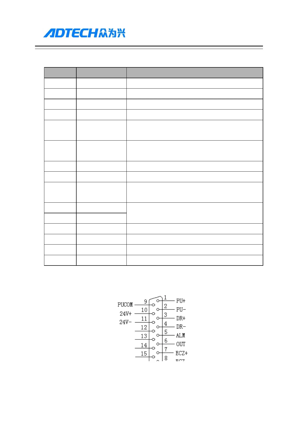
Standard pulse wiring diagram
XS1 … XS4 Pulse Interfaces Standard Wiring

Table of Contents

Related product manuals