ADTECH4 SeriesCNC Maintenance Manual
This wiring is suitable for 46 series and 49 series controller;
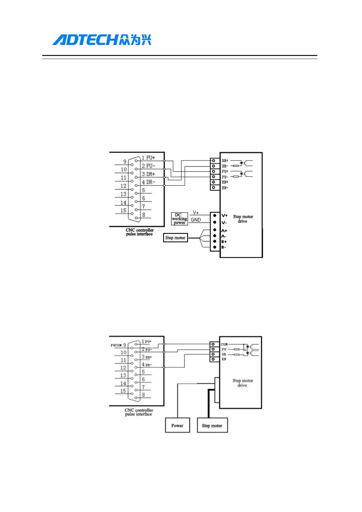
Step motor drive cable to differential input
Adtech CNC drive is for reference, all of which use differential input mode. This mode has strong
anti-interference and is recommended. Please refer to the figure below for the connection of CNC with step
motor drive and step motor
Step motor drive wiring diagram for single-ended input
Certain companies connect together the optocoupler input cathodes of step drives, i.e. common cathode
connection, which isn’t suitable for CNC controller. Common anode connection connects together the anodes
of optocoupler input. The wiring shall follow the figure below, and do not connect PU+ and DR+ together, or
else the pulse interface may be damaged.
Wiring Diagram for Step Motor Drive with Common Anode Input
Servo motor drive wiring diagram (note: only applicable for 46 series controller)