ADTECH4 SeriesCNC Maintenance Manual
Since differential connection is used in most cases, please refer to differential mode for the pulse
connection. Most servo drives require 12-24V power supply, and the 24V power provided by pin 10, 11 is
available. The specific connection depends on servo drive. Please contact us if you have any question.
Caution
Either two of PU+, PU-, DR+ and DR- shouldn’t be connected, or else the pulse interface may be damaged.
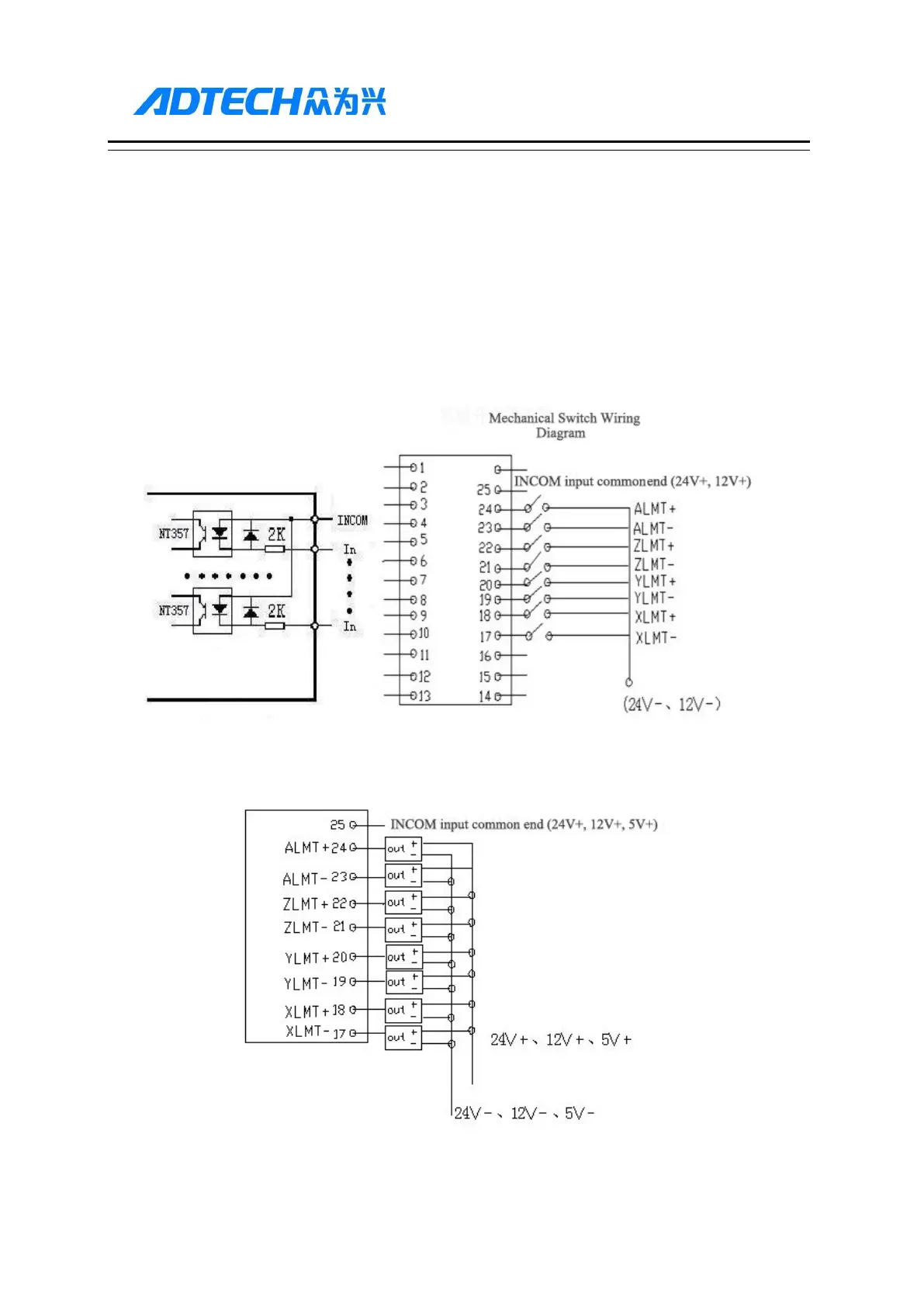
12.2.2. Digital input interface
The digital input interface contains the hard limit signal of every axis, and the definition follows:
Simple Internal Output Diagram for Digital Input Photoelectric Switch Wiring Diagram