ADTECH4 SeriesCNC Maintenance Manual
12.
Hardware Interface Definition and Connection Instructions
12.1
Installation Layout
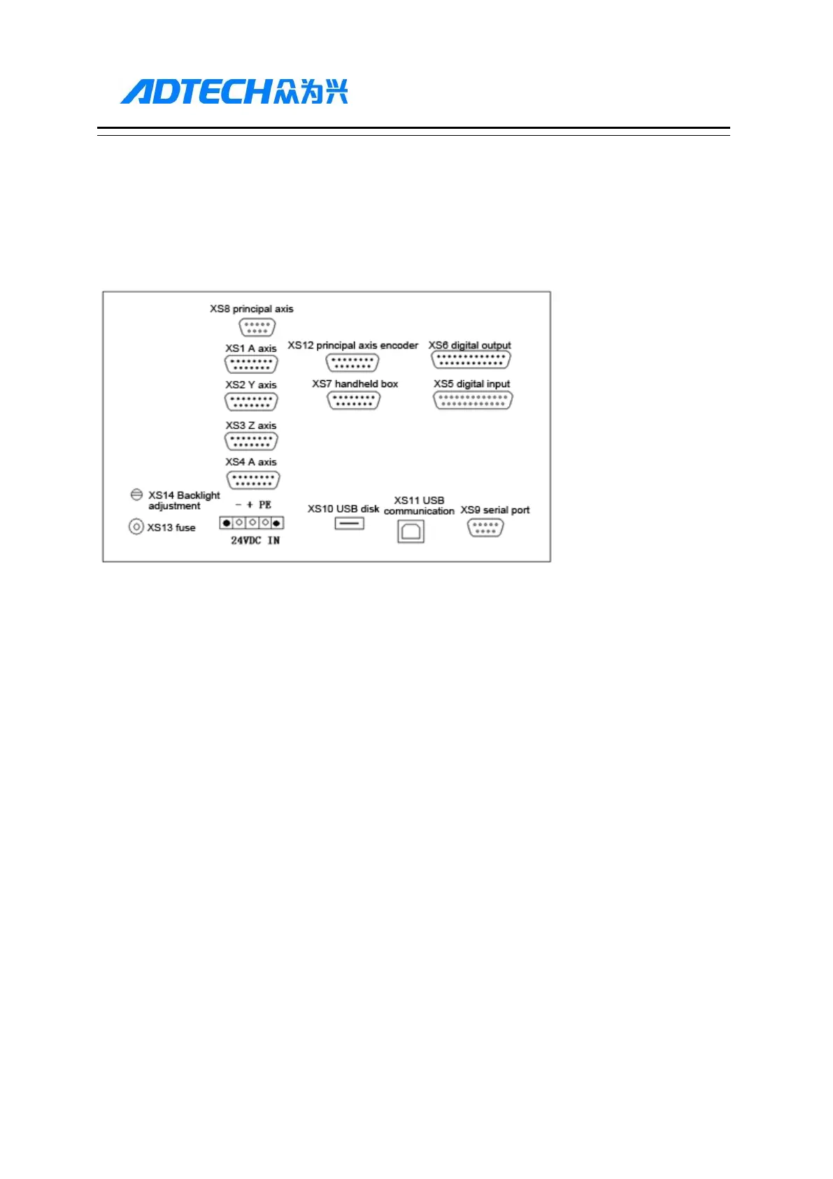
12.1.1. 46 Series External Interface Diagram
XS1(X axis), XS2(Y axis), XS3(Z axis), XS4(A axis):
15-core D-pin socket connects to step motor drive or digital AC servo drive
(2) XS5 digital input:
25-core D-pin socket inputs signals for every axis limit and other switching quantity
(3) XS6 digital output:
25-core D-pin socket outputs signals for switching quantity
(4) USB and serial port exchange files between PC and NCT-XX controller and realize other functions.
(5) NCT-XX controller uses 24V DC power supply, and the internal power consumption is about 5W.
(6) XS7 accessory panel:
15-core D-pin socket connects to hand wheel
(7) XS8 principal axis:
9-core D-pin socket connects to principal axis inverter
12.1.2. 49 Series External Interface Diagram