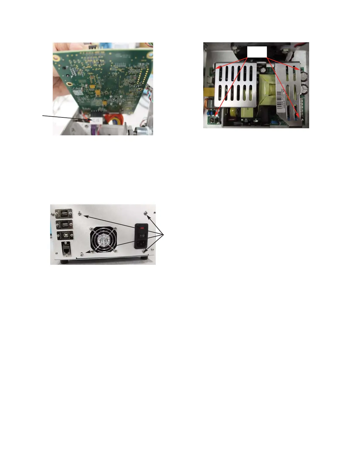
12. Remove the four screws and washers that
mount the Cage to the Power Supply &
Controls Assembly. Slide the Cage off of
the assembly (
Figure 8).
13. Unplug the P100, P101 & P300
Connectors from the Power Supply).
14. Remove the four screws that secure the
Power Supply to the Power Supply &
Controls Assembly (
Figure 9).
15. Mount the replacement Power Supply to
the Power Supply & Controls Assembly
using four screws.
16. Plug the P100, P101 & P300 Connectors
into the Power Supply.
17. Slide the Cage onto the Power Supply &
Controls Assembly, and secure it using
the four screws and washers.
18. Plug the C12 Connector into the bottom
of the Control PCB:
19. Secure the Control PCB to the Power
Supply & Controls Assembly using the
six screws.
20. Slide the Power Supply & Controls
Assembly into the Base Assembly, and
secure it to the rear of the Chassis using
the two screws.
21. Rest the instrument on its back side.
Secure the Power Supply & Controls
Assembly to the bottom of the Chassis
using the two screws.
22. Place the instrument in the upright posi-
tion. Plug the three USB Cables and the
Ethernet Cable into the Ports located on
the Power Supply & Controls Assembly
Figure 7
Figure 8
Figure 9
707011RPM Rev0
(OsmoPRO Service Manual)
Page 3 of 4
C12
Connector
Four Screws
Four
Screws