www.advancedco.com
108
Circuit Type
Circuit
Function
Wire Types
Maximum
Distance
Typica
l Wire
Size
(AWG)
Comments
IDCs
(power limited)
SLC based
initiating
device input
circuits &
conventional
smoke
zones
Untwisted Unshielded,
Twisted Pair or Twisted
Shielded Pair.
300 feet 18-20
AWG
EOL resistor value varies depending upon module.
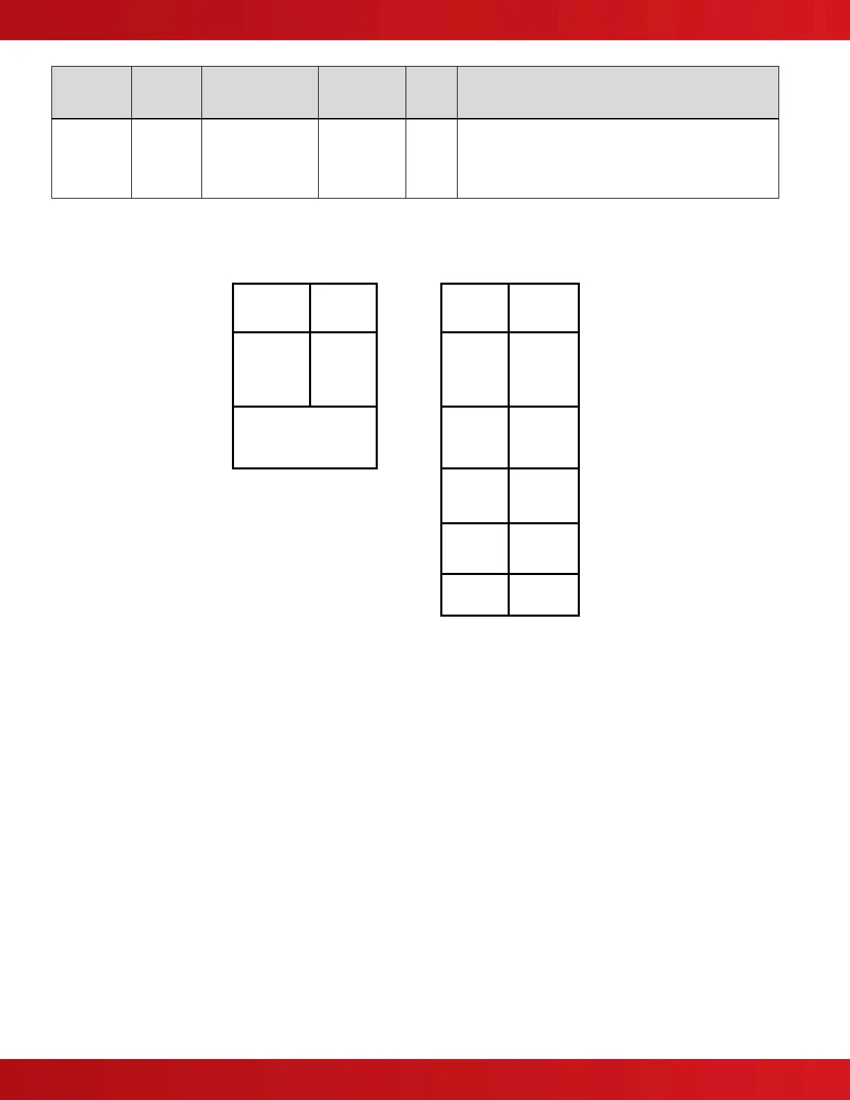
Note #1: SLC (Signaling Line Circuit)
Maximum circuit impedance depends on the SLC loop load current. The voltage drop (load current x cable resistance) over the
cable always needs to be taken into account to ensure the devices are receiving an adequate supply voltage (see table below):
Maximum
Circuit
Impedance
72Ω
Circuit
Loading
Max.
Circuit
Impedance
Insulation
Resistance
(Core-Core
and Core-
Screen)
2M Ω 100mA 55.0Ω
NB: Maximum Circuit
Impedance is the sum of
the resistance of both
cable conductors.
200mA 27.5Ω
300mA 18.3Ω
400mA 13.7Ω
500mA 11.0Ω
Note #2: Notification Appliance Circuit
The voltage drop on notification appliance circuit should be calculated to ensure that the minimum voltage at the end of the
circuit exceeds the minimum required by each notification appliances at the minimum alarm circuit output voltage.
The voltage at the end of the circuit is given by:
Minimum Alarm Voltage = V
OUT(MIN)
– (I
ALARM
x R
CABLE
)
Minimum Output Voltage (V
OUT(MIN)
) is V
BAT(MIN)
– 0.5V = 20.5V
Alarm Current (I
ALARM
) is the sum of the loads presented by the notification appliances in alarm
Cable Resistance (R
CABLE
) is the sum of the cable resistance in both wires x cable length.
Typical wire size resistance (R
CABLE
): Loop Resistance (2 Wires)
18 AWG solid: Approximately 6.5ohms/1000ft. 13ohms /1000ft.
16 AWG solid: Approximately 4.1ohms/1000ft. 8.2ohms /1000ft.
14 AWG solid: Approximately 2.6ohms/1000ft. 5.2ohms /1000ft.
12 AWG solid: Approximately 1.8ohms/1000ft. 3.6ohms /1000ft.