www.advancedco.com
38
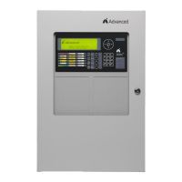
4.2.1.9 AX-CTL Ancillary Contact Monitoring Input
AX-CTL provides an ancillary contact monitoring input
which allows the AX-CTL to monitor any normally closed
contact for supervision. If the contact opens a trouble/fault
is generated by the AX-CTL. This input is normally utilized
for AX-PSU and in a hardwired audio amplifier installation
for the AX-PSU-6 and AV-AMP-80 trouble/fault monitoring.
This input can also be utilized for any trouble/fault
monitoring.
Note: The AX-CTL-1PCB one loop base card cannot
support the AX-PSU option module.
4.2.1.10 AX-CTL-2PCB Ancillary AX-PSU DC Power
Input
The AX-CTL-2PCB provides an ancillary AX-PSU DC
power input which allows an additional 5 Amp, 24 VDC
power to be supplied to the AX-CTL-2PCB base card. This
additional power is specifically for notification appliance
circuit power requirements when the AX-LPD or AX-NAC
modules are utilized. When utilizing the AX-PSU auxiliary
power supply separate batteries are not required.
Note: The AX-CTL-1PCB, one loop base card, cannot
support the AX-PSU, AX-LPD or AX-NAC option
modules.
Nominal 27.4 VDC, temperature compensated to track
main panel DC supply.
By adding an optional AX-PSU power supply additional
power is available for the NAC-3 and NAC-4 circuits of the
AX-LPD or AX-NAC module.
A Molex cable assembly from the AX-ACB provides AC
power to the AX-PSU Auxiliary Power Supply.
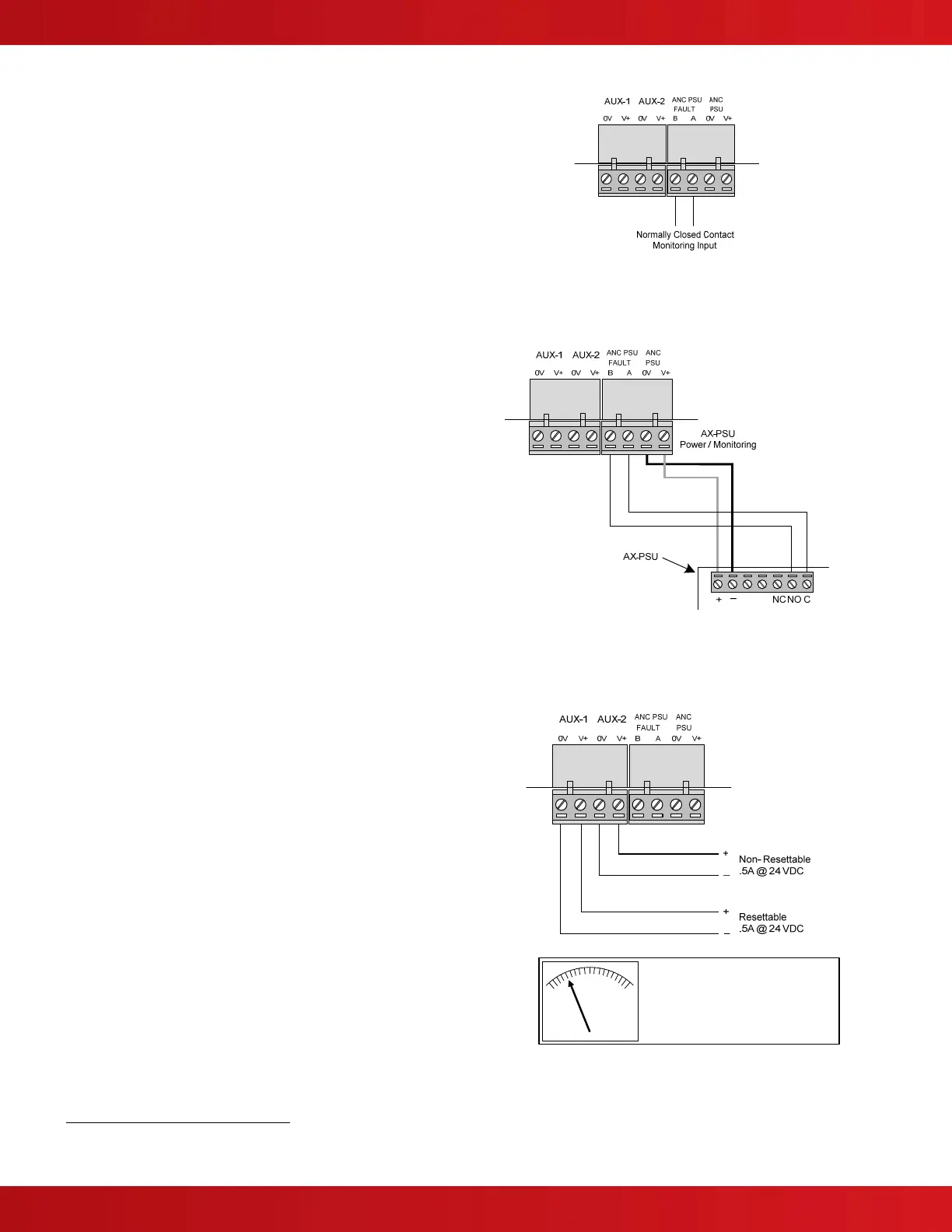
4.2.1.11 AX-CTL AUX Supply Outputs
The AX-CTL provides two 24 VDC power outputs, one
resettable and one non-resettable.
The power output ratings are as follows:
SPECIAL APPLICATION CIRCUITS
18.0 – 28.0 VDC @ 0.5A
3
(each)
SUPERVISED, POWER LIMITED.
AUX #1: 4-wire smoke detector power or other similar
application. Power turns off for 10-15 seconds
on reset.
AUX #2: 24 VDC (nominal) power output for internal
peripheral cards or external equipment.
Wire range – 22-12 AWG
Note: Use appropriately sized wire for the current load
to ensure device compatibility.
3
TOTAL OUTPUT LOAD must not exceed panel supply rating – maximum 5A (10A if AX-PSU installed).
The following meter readings are
available on the FACP display:
AUX#1 Load Current
AUX#2 Load Current
(Refer to Section 10.1.1)