www.advancedco.com
72
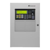
5 Recommended Cable Routing
Power limited and non-power limited circuit wiring must remain separate in the fire alarm system enclosure. All
power limited circuit wiring must remain at least 0.25” (6.35 mm) away from any non-power limited circuit wiring.
Furthermore, all power limited and non-power limited circuit wiring must enter and exit the enclosure through
different knockouts and/or conduits (see figure 46).
Below is a typical diagram for the Axis
AX
; AX-CTL-1L, AX-CTL-2 and AX-CTL-4 to meet the above mentioned power
limited wiring requirements:
LINE 1
HEARTBEA
T
LINE 2
SYS
TROUBLE
+ + - - A
B
1 2 3 4 5 NC C NO
Figure 46 -
X-CTL-1L, AX-CTL-2 or
X-CTL-4 Cable Routing