www.advancedco.com
62
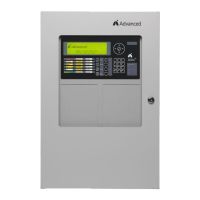
4.11 Auxiliary - Reverse Polarity Signaling
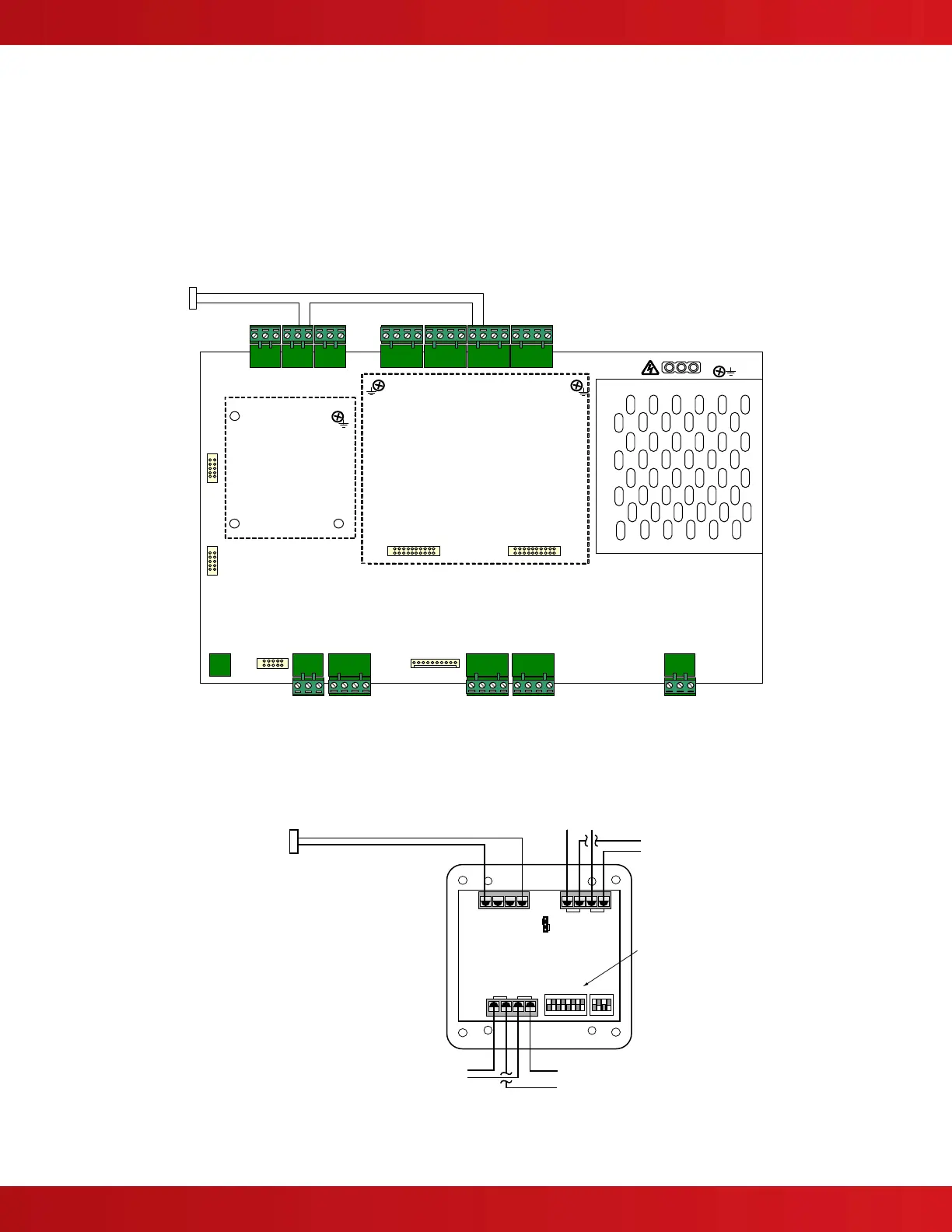
The following is a wiring diagram utilizing a NAC circuit or 55000-825ADV addressable NAC module for reverse
polarity signaling to a remote location (see figure 36).
Note: A “Not” statement will need to be created for the trouble contact activation, so that an alarm
condition has a higher priority than a trouble condition (consult factory).
E
O
L
L1L2
+
-
+
-
To N ex t
AX Series
Peripheral
From
AX Series
SLC Loop
47K
1/2 Watt
Programming
DIP Switches
A/B+
A/B-
A+A-
12345678
1
2
4
8
16
32
64
NO
B
S1
A
10
1234
1
2
4
8
NO
10
S2
TB2
TB3
TB1
SOUNDER
PA
Vext - Vext+
+
-
-
+
24 VDC In
(NonResettable Power)
24 VDC Out
(NonResettable Power)
* Set Jumper
to Sounder
J1
To Line Reversal Receiving Equipment
* If trouble reporting is required ,
run A/B+ thru either the Base
Card trouble relay or thru an
addressable relay programmed as
inverted, trouble activation.
*
NC NO COM
SUPERVISORY
NC NO COM
TROUBLE
NC NO COM
FIRE
USB RS232 PBUS
AUX DC
OUT
DC IN BATTERYO/C OUT
OUT OUT IN IN
+ - + -
LOOP-1
Line Reversal Remote Signaling
To Line Reversal Receiving Equipment
* If trouble reporting is required , run A/B+ thru either the
Base Card trouble relay or thru an addressable relay
programmed as inverted, trouble activation.
*
E
O
L
10K
AX-LPDAX-NET
Figure 36 - Reverse Polarity Wiring