www.advancedco.com
39
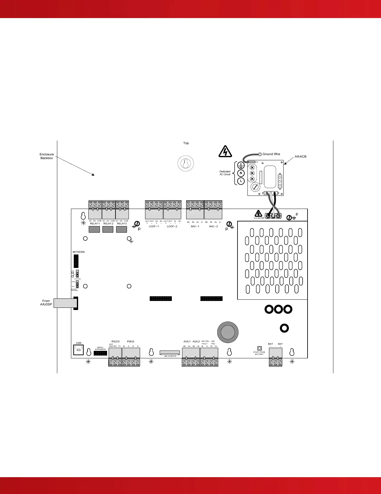
4.2.2 Replacing the AX-CTL Base Card
If replacing the AX-CTL base card, remove power (AC and battery) from the system. Remove all field wiring
terminal blocks from the AX-CTL and disconnect the Molex connector cable originating from the AX-ACB board.
Disconnect the flat ribbon cable attached to the AX-DSP, Alphanumeric Graphical Display, and remove the three (3)
screws [p] securing the AX-CTL to the back box. Carefully slide the AX-CTL up and off of the five top-hat (screw-
less [
*
]) standoffs (see figure 17).
Carefully slide the new AX-CTL over the five top-hat (screw- less [
*
]) standoffs, and insert/tighten the previously
removed three (3) screws [p]. Reconnect the removed Molex connector cable originating from the AX-ACB board,
plug in the flat ribbon cable attached to AX-DSP display, and reinstall all removed field wiring terminal blocks.
Reconnect AC and battery power.
Failure to tighten the screws will defeat the protection circuitry designed to protect the module from
damage due to lightning and static electricity.
Figure 17 - AX-CTL Base Card