www.advancedco.com
67
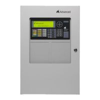
4.14.1.1 AX-PSU DC Wiring
The AX-PSU is a 27.4 VDC temperature compensated power supply
designed to track the AX-CTL DC supply.
The power from the AX-PSU is used to supply additional power to
the NAC-3 and NAC-4 notification appliance circuits in lieu of power
being drawn from the AX-CTL base card. A cable is supplied with
the AX-PSU for connection to the AX-CTL base card, interfacing the
DC power and fault monitoring (see adjacent drawing).
If replacing the AX-PSU, Remove AC and DC power. Remove the
AC power lead and the wiring interfacing the AX-PSU to the AX-CTL
base card. Remove the four (4) screws securing the AX-PSU to the
back box and remove. Position the new AX-PSU onto the back box
standoffs and secure with the four (4) removed screws. Rewire the
removed AX-CTL base card interface wiring and reconnect AC
power lead.
Failure to tighten the screws will defeat the protection circuitry designed to protect the module from
damage due to lightning and static electricity.
4.15 AX-RL8 Eight Relay Output Module
The AX-RL8 eight relay output module is an eight (8) point relay module that connects directly to the AX-CTL base
card.
Note: If an AX-RL4, AV-AMP-80 or AX-CZM module is installed in the Axis
AX
enclosure an AX-RL8 eight
relay output module cannot be added.
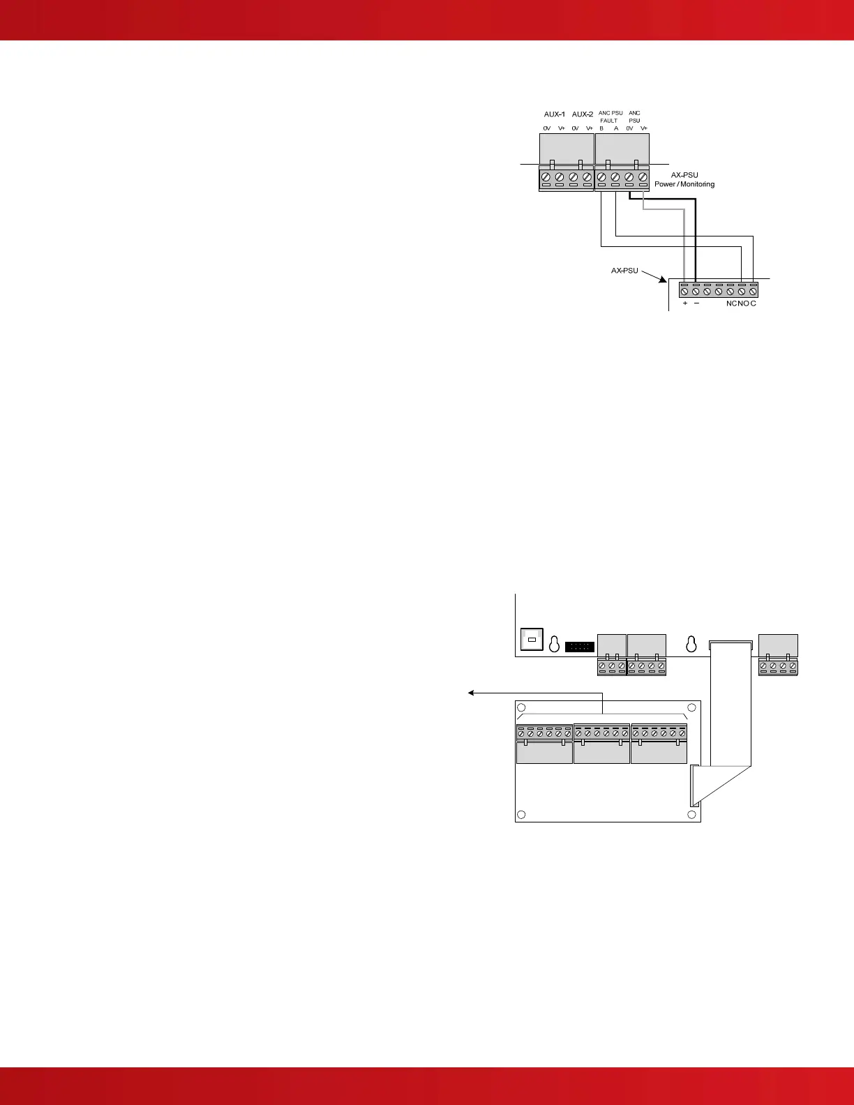
4.15.1 Adding or Replacing an AX-RL8 Module
If adding an AX-RL8 module, mount the AX-RL8 to the
standoffs in the position shown to the right and secure using
the four (4) supplied screws.
Failure to tighten the screws will defeat the protection
circuitry designed to protect the module from damage
due to lightning and static electricity.
Connect the AX-RL8 to the AX-CTL base card “O/C
OUTPUT” header with the supplied flat ribbon cable (the
cable is polarized to ensure correct orientation).
If replacing the AX-RL8 module, remove AC and DC power.
Remove the three (3) pluggable terminal blocks and the flat
ribbon cable originating from the “O/C OUTPUT” of the AX-
CTL base card. Remove the four (4) screws holding the
module to the back box. Position the new module onto the
back box standoffs and secure with the four (4) removed
screws. Reconnect the three (3) removed pluggable terminal
blocks and the flat ribbon cable originating from the “O/C
OUTPUT” of the AX-CTL base card.
Failure to tighten the screws will defeat the protection circuitry designed to protect the module from
damage due to lightning and static electricity.
USB
O/C OUTPUT
P-BUS
EXT
GND
RX
SERIAL
EXPANSION
BBAA
RS-232
TX 0V0V V+V+
AUX-1 AUX-2
Ribbon Cable
Recommended Field Wire Routing