www.advancedco.com
45
4.4.3 Installing the AV-AMP-80 Audio Amplifier Module
The AV-AMP-80 audio amplifier module provides digital audio capabilities for the Axis
AX
Intelligent Fire Alarm
Control Panel. It requires separate 24 VDC originating from an AX-PSU-6 power supply charger. As previously
indicated the AV-AMP-80 audio amplifier module is mounted below the AX-CTL base card on the left side of the
back box (see figure 21).
To install the AV-AMP-80 audio amplifier module slide the AV-AMP-80 mounting plate tabs under the two (2) tabs
located on the lower left side of the back box below the AX-CTL base card. Secure the top end of the AV-AMP-80
mounting plate to the back box standoffs with the provided two (2) screws (see figures 24).
Note: The AV-AMP-80 is pre-assembled on a mounting plate, do not remove from the mounting plate as
this is part of the assembly and is required for heat sinking the AV-AMP-80. If replacing, the new AV-AMP-
80 will be supplied pre-assembled to a mounting plate.
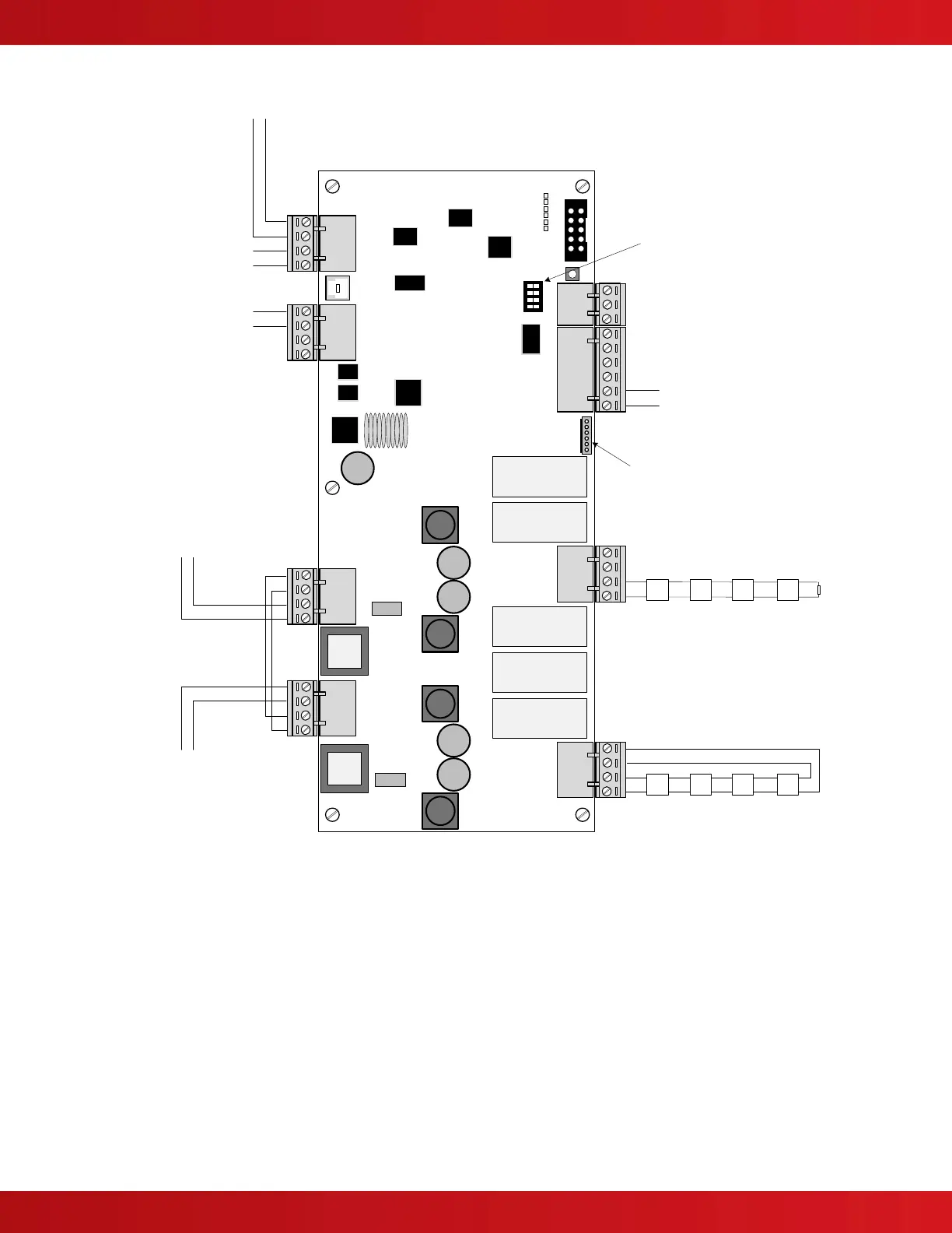
OUT- OUT+ IN- IN+
AMP1
OUT- OUT+ IN- IN+
AMP2
+24V GND +24V GND
POWER
B A B A
RS485
AMP-1
A+ A- B- B+
AMP-2
A+ A- B- B+
INPUTS
IN1 GND IN2 GND IN3 GND
TROUBLE
COM NO NC
TX
HB
AMP1
AMP2
40V
USB
4.7K EOL
Microphone Bus Input
To Dedicated AX-PSU-6
24VDC (terminals 0V and +V0)
To AX-CTL Base Card
PBUS (RS-485)
Class B Only
Class “A” Wiring
Class “B” Wiring
Installed Microphone Supervision Plug
To Dedicated AX-PSU-6
Trouble Relay Contact
(terminals COM and NO)
SS S S
SS S S
Microphone Bus EOL (end-of-line) or to
next AV-AMP-80 Area Amplifier
PBUS (RS485)
Address Switch
To Next PBUS
(RS-485) Module
Two (2) Class A or B Area Amplifier Circuits (circuits
activate in tandem)
Note: In the AV-AMP v1.1.1 or higher, amplifier
message programming tool, amplifier 2 can be
configured as a backup to amplifier 1.
Figure 23 – Floor (Area) AV-AMP-80 Amplifier