www.advancedco.com
64
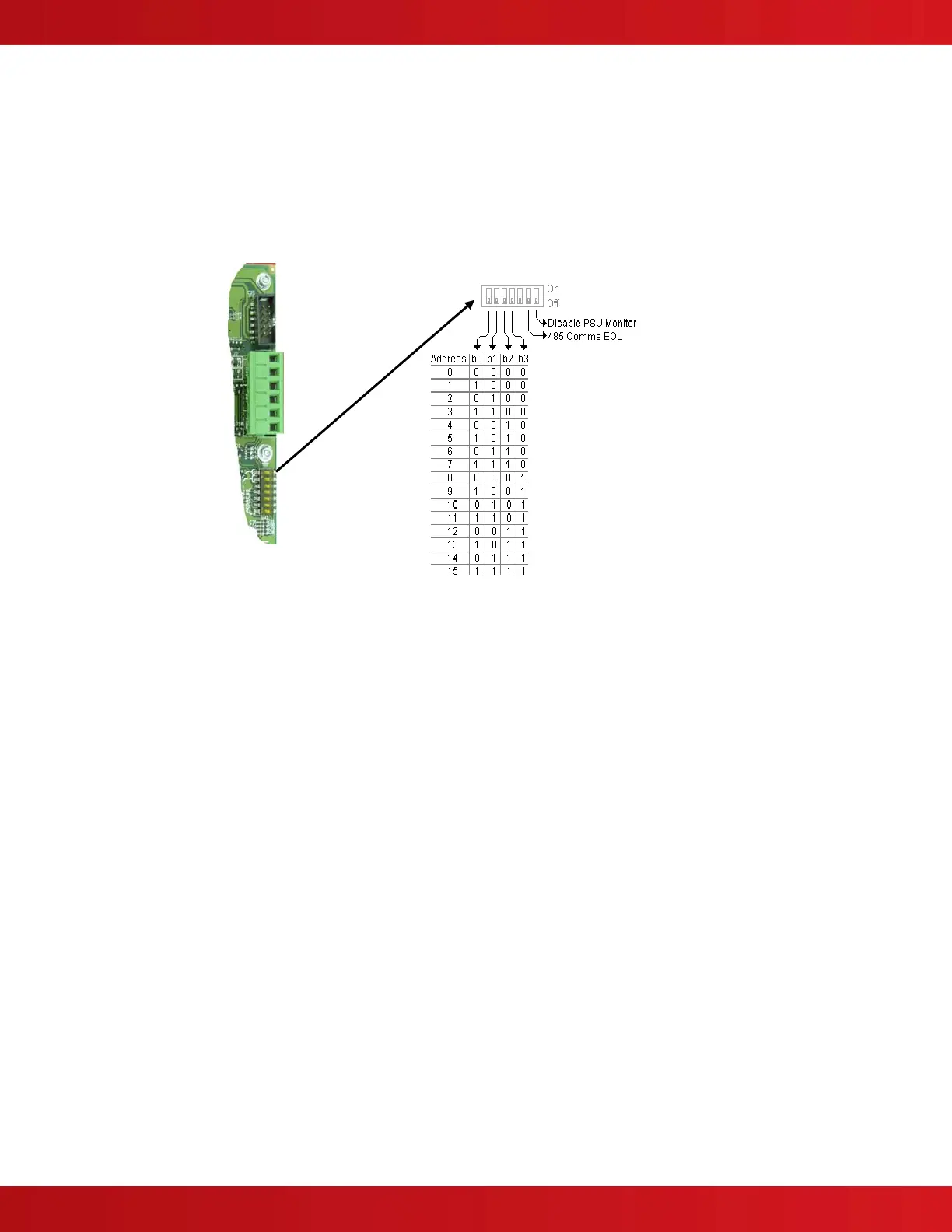
4.12.2 Addressing Switch LED Modules
Each switch LED module must be connected to the AX-CTL-1L, AX-CTL-2 or AX-CTL-4 intelligent fire alarm control
panel’s AX-CTL base card P-BUS (RS485). As the switch LED modules reside on the AX-CTL PBUS (RS485),
each module must be configured with a unique address (see figure 38). The address setting corresponds to PBUS
programming criteria utilized within the Advanced PC-NeT field configuration program.
As previously stated, up to sixteen (16) switch LED modules (any combination) can be connected to a single AX-
CTL base card peripheral bus (PBUS).
4.12.3 Switch LED Module Wiring
As previously indicated, each switch LED module requires connection to the AX-CTL-1L, AX-CTL-2 or AX-CTL-4
intelligent fire alarm control panel’s AX-CTL base card P-BUS (RS485). In addition, each switch LED module
requires 24VDC filtered and regulated power.
4.12.3.1 24VDC Wiring
24 VDC power for switch LED modules can come from any fire alarm listed 24 VDC filtered and regulated power
supply (AX-CTL AUX [non resettable] power, AX-PSU-6, AX-PSN or other fire alarm listed power supply). Wire 24
VDC filter regulated power to terminals + and – of the switch LED module (see figure 39).
Refer to Axis
AX
Wiring Guide Section Error! Reference source not found..
Note: The Switch LED Module is capable of monitoring a remote listed 24 VDC filtered regulated power Note: The Switch LED Module is capable of monitoring a remote listed 24 VDC filtered regulated power
supply for trouble conditions. Wire the trouble N/O contact (fail-safe [closed unless trouble]) to PSU
monitoring terminals of the switch LED module (see figure 39) and confirm DIP switch 7 “Disable PSU
Monitoring” of the Switch LED Module is set to the “OFF” position (see figure 38).
4.12.3.2 PBUS (RS485) Wiring
Connect the PBUS (RS485) terminals A and B of the AX-CTL base card to the 485 (PBUS) A and B input terminals
of the switch LED module (see figure 39). If this is the last module connected to the AX-CTL PBUS (RS485), set
DIP switch 6 “485 Comms EOL” on the Switch LED Module to the “ON” position (see figure 38).
Refer to Axis
AX
Wiring Guide Section 9.
Note: When utilizing multiple switch LED module’s on the same inner door row, 24 VDC power and the
PBUS (485) wiring can be daisy chained from the first switch LED module to the next (see figure 40).
Figure 38 – Switch LED Module Addressing