www.advancedco.com
68
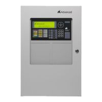
4.15.2 AX-RL8 Output Wiring
Relays 1 and 2 are Form C relays. Relays 3 thru 8 are
Form A, but can be programmed inverted.
All outputs are field programmable (default setting is set
to activate on common alarm).
30 VDC/AC @ 1.0A, PF=1 (resistive)
POWER LIMITED – Connect to power limited circuits
only.
Wire range – 22-12 AWG
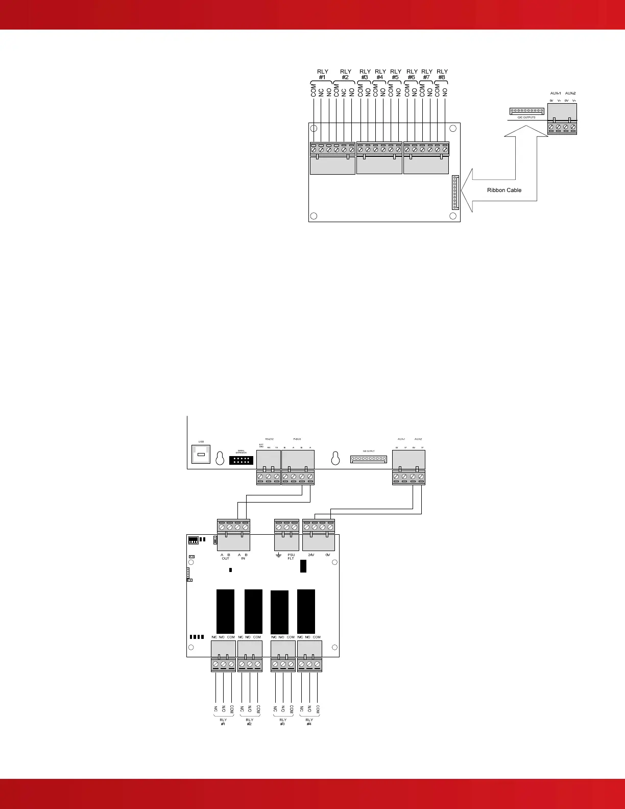
4.16 AX-RL4 Four Point Relay Output Module
The AX-RL4 four point relay output module is an optional PBUS (RS485) module for use the AX-CTL-1L, AX-CTL-2
or AX-CTL-4 intelligent fire alarm control panel’s AX-CTL base card. The AX-RL4 provides four (4) fully field
programmable Form “C” relay contacts for project specific control functions. The AX-RL4 is listed to switch DC or
AC voltage and up to sixteen (16) AX-RL4 modules can be connected to a single AX-CTL base card providing a
maximum of 64 relay outputs.
The AX-RL4 can either mount onto the four (4) standoffs located on the left-hand side of the Axis
AX
enclosure below
the AX-CTL base card (see figure 41) or within an AXM-009 enclosure (see figure 42).
Note: If an AX-RL8, AV-AMP-80 or AX-CZM module is installed in the Axis
AX
Intelligent Fire Alarm Control
Panel an AX-RL4 module cannot be added. However, the AX-RL4 module can be mounted remotely in an
AXM-009 or AX-GCAB enclosure.
Refer to AX-RL4 Installation Manual for detailed information regarding installation.
Figure 41 - AX-RL4 Axis
Enclosure Mounting