www.advancedco.com
56
4.8.2 AX-NET4 or AX-NET7 Module Wiring
Each AX-NET4/AX-NET7 module has independent connectors for the outgoing and incoming network wiring.
Utilizing twisted shielded cable, connect from the “OUT” terminal on the first panel, to the “IN” terminal on the next
panel, as follows:
OUT
Shield
B
A
Shield
B
A
IN
SHIELD
B
A
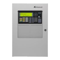
4.8.2.1 AD-NeT-PluS Class B Wiring
The “IN” terminals on the first node and the “OUT” terminals on the last node are not used. Connect an end of line
filtering resistor (150Ω) between A and B on the unused terminal blocks.
Maximum overall cable length is 5000ft (1500m) using recommended cables.
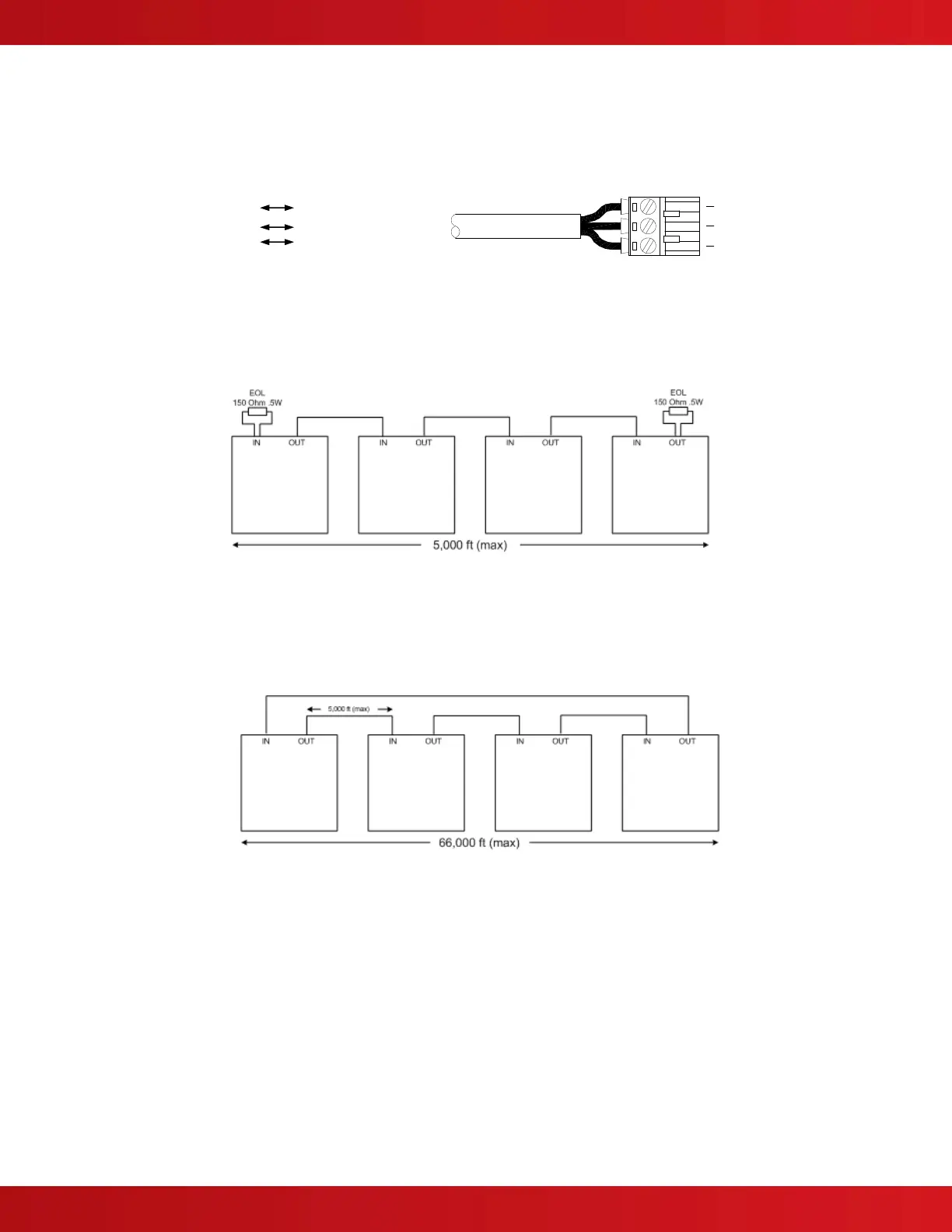
4.8.2.2 AD-NeT-PluS Class A Wiring
When utilized all network nodes must be installed with Class X (Class A, Style 7) type adaptor card.
Install a cable from the last node “OUT” terminals back to the first node “IN” terminals to form a loop “ring”.
Maximum cable length between nodes is 5000ft (1500m) using recommended cables.
Maximum overall cable length is 66000ft (20000m) using recommended cables.
4.8.3 Replacing the AX-NET4 or AX-NET7 Module
Remove power (AC and battery) from the system. Remove the screw [p] securing the module to the AX-CTL base
card and snap the module free from the nylon spacers [n]. Unplug the flat ribbon cable connected to the network
connector on the AX-CTL base card. Plug the flat ribbon cable of the new module into the dedicated network
connector on the base card. Position the module onto the three (3) nylon spacers and snap in place. Secure the
module in place by screwing the removed screw [p] into the metal hexagon spacer [h] (see figure 30). It is critical
that this screw is tightly secured, as the screw is required for the earth ground connection to the AX-NET4/AX-NET7
module. Reconnect AC and battery power to the system.
Failure to tighten the screw will defeat the protection circuitry designed to protect the module from damage
due to lightning and static electricity.