www.advancedco.com
92
7.8.1.2 View Inputs
This function shows the current operational state and condition for all zones and individual inputs (including
zones/points of other network nodes). The display presents a list of all of the zones containing input devices, with
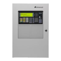
the first zone highlighted. For example:
[Inputs] More>
Zone Mode Location
0001 Enabled BASEMENT WEST
0002 ALL DISABLED BASEMENT EAST
0008 Enabled GROUND FLOOR
0009 Enabled MAIN RECEPTION AREA
Press the buttons to highlight the required zone and then press the button to view the full location text.
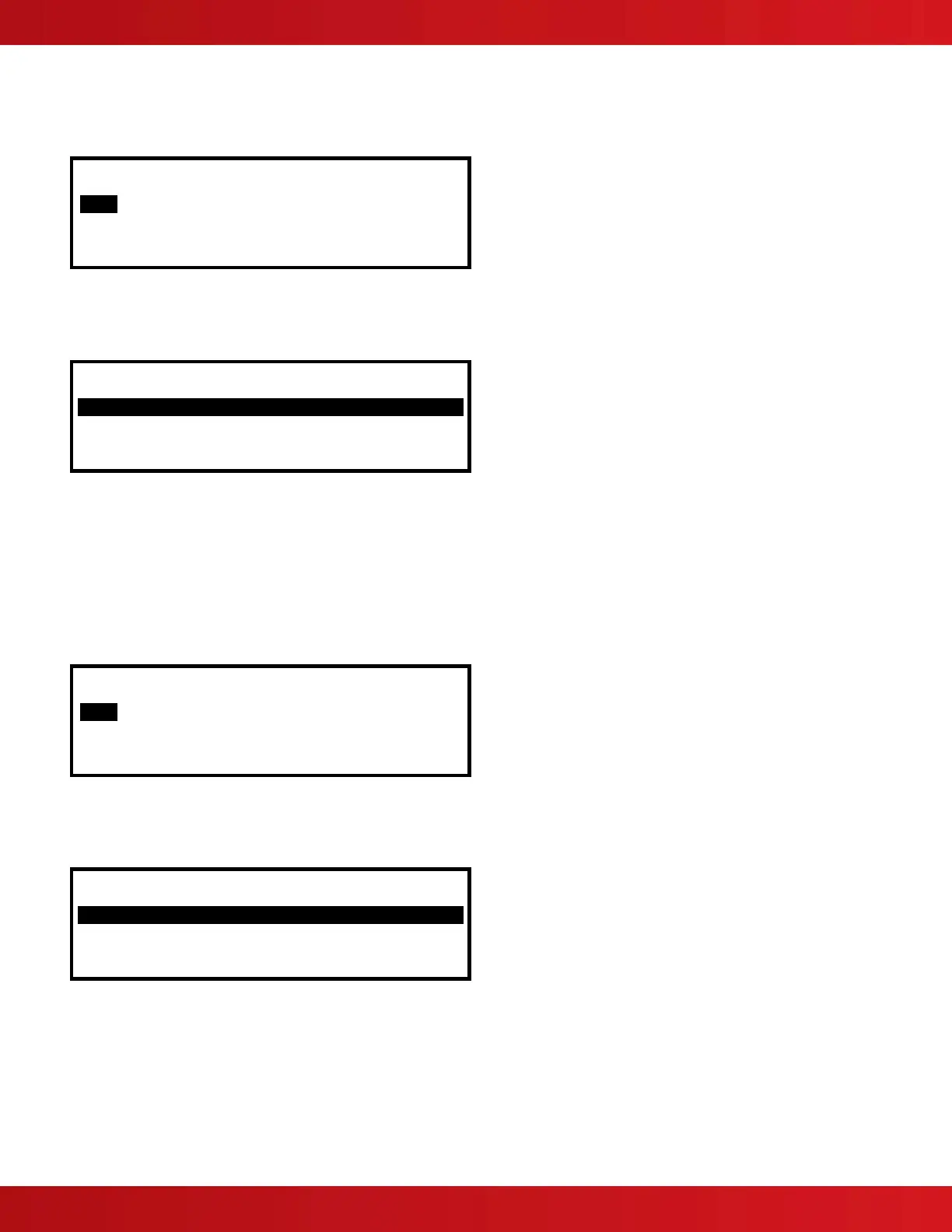
Press the button again to view additional information and the inputs within the zone and their status. For example
button pressed 6 times:
[ Inputs in Zone 0008] <More
Mode Lp Adrs Sector Node
Enabled 1 001.0 1 1
Disabled 1 002.0 1 1
Enabled 1 003.0 1 1
Enabled 1 004.0 1 1
The display shows the current disabled condition (mode) for each input, as either enabled or disabled. In addition,
the SLC loop (Lp), address (Adrs), sector and node number.
Press the buttons to scroll through the inputs.
Pressing the button will show further information on device location, type, analog/digital values, etc.
Press the “Esc” button to return to previous view.
7.8.1.3 View Outputs
This function shows the current operational condition for all outputs (including outputs of other network nodes).
[Outputs] More>
Zone Mode Location
0008 ENABLED GROUND FLOOR
0100 ENABLED MAIN RECEPTION
Press the buttons to highlight the required zone.
Press the button again to view additional information and the outputs within the zone and their status. For
example button pressed 6 times:
[ Outputs In Zone 0008] <More
Mode Lp Adrs Sector Node
Enabled 1 032.0 1 1
Enabled 1 056.0 1 1
Enabled 2 011.2 1 1
Enabled 3 026.2 1 1
Note: A * symbol preceding the state (e.g. *On) indicates the device has been configured as an inverted
output (i.e. a trouble relay that is designed to de-energize when a trouble occurs).