EasyManua.ls Logo

Advanced Axis AX-CTL-1L User Manual

Advanced Axis AX-CTL-1L
118 pages
To Next Page IconTo Next Page
To Previous Page IconTo Previous Page
Page #42 background image
www.advancedco.com
42
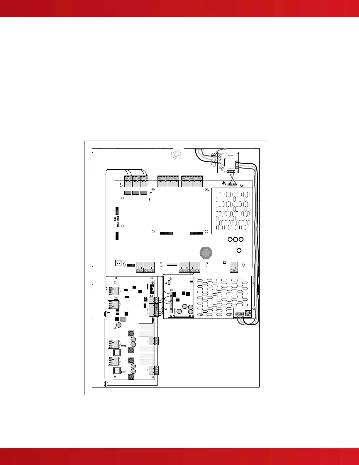
4.4 AV-AMP-80 Audio Amplifier Module
A AV-AMP-80 audio amplifier module with associated AX-PSU-6 power supply charger module can be added to
any Axis
AX
Intelligent Fire Alarm Control Panel to create an audio signaling or remote audio booster panel
[hardwired or PBUS (RS485)]. The AV-AMP-80 gets mounted below the AX-CTL base card on the left side of the
back box (see figure 21).
Refer to Axis
AX
Wiring Guide Section 9.
Note: If utilizing an AV-AMP-80 audio amplifier module with an Axis
AX
Intelligent Fire Alarm Control Panel
(non “V”) it is for audio signaling and remote audio booster operation only. Non “V” panels do not support
the AV-MIC microphone assembly. In addition, when an AV-AMP-80 audio amplifier module and AX-PSU-6,
power supply charger module are utilized, the Axis
AX
Intelligent Fire Alarm Control Panel cannot support an
AX-PSU expansion power supply. As previously indicated, the AX-CTL-1L cannot support an AX-PSU, AX-
LPD or AX-NAC option module; however, it can support an AV-AMP-80 audio amplifier module and AX-PSU-
6 power supply charger module.
USB
O/C OUT PUTS
OUT
+
OUT
-
IN
+
IN
-
LOOP - 1
NC NO COM
RELAY 1
NC NO COM
RELAY 2
NC NO COM
NETWORK
A.C. MAINS!
ANC PSU ANC
FAULT PSU
P-BUS
EXT
GND
RX
SERIAL
EXPANSION
BAT BAT
-+
START FROM
BATTERY
PROG
RUN
LOCK M EM
MASTER PROGRAM
RELAY 3
LOOP - 2 NAC - 1 NAC - 2
OUT
+
OUT
-
IN
+
IN
-
A+B+ A-B- A+B+ A-B-
BBAA
RS-232
TX 0V0V V+V+
AUX-1 AUX-2
0VBV+A
L
N
Ground Wire
TX
HB
AMP1
AMP2
40V
USB
*
*
Figure 21 – Optional AV-AMP-80 and AX-PSU-6

Table of Contents

Questions and Answers:

Advanced Axis AX-CTL-1L Specifications

General IconGeneral
BrandAdvanced
ModelAxis AX-CTL-1L
CategorySecurity System
LanguageEnglish

Summary

1 Introduction and Overview

1.1 Product Description

Details the AX-CTL-1L, AX-CTL-2, AX-CTL-4 panels and their features.

1.4 General Installation Notes

Provides essential installation guidelines and precautions for the system.

2 Agency Listings and Requirements

2.1 ANSI/UL864

Product listing for various services and applications.

3 Enclosure Installation

3.1 Enclosure Mounting and Dimensions

Details enclosure mounting options and overall dimensions.

3.2 Inner Door Assembly

Covers inner door assembly and aperture modules.

4 Circuit Card Installation and Electrical Specifications

4.2 AX-CTL Base Card

Describes the main AX-CTL-1PCB/2PCB base card and its features.

4.3 AX-DSP Alphanumeric Graphical Display

Describes the user interface display and its input capabilities.

6 Loading Calculations

6.1 Panel Loading Calculations

Discusses load calculations for panel components and battery requirements.

7 Operation

7.1 User Controls and Indications

Explains panel controls (keys) and status LEDs.

7.2 LCD Indications

Describes panel display messages for various conditions.

7.8 User Menu Functions

Overview and description of user menu options.

9 AxisAX Wiring Guide

9.1 General Wiring Guidelines

Provides guidelines for circuit wiring types and distances.

10 Maintenance & Troubleshooting

10.1 Troubleshooting

General troubleshooting guidance for the system.

10.2 Replacement of Components

Procedures for replacing components like batteries and displays.