www.advancedco.com
36
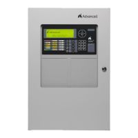
The default operation of each notification appliance circuit is non-synchronized, turn ON steady for any alarm
condition and turn off when silenced or reset. If non-silenceable synchronization strobes are programmed, strobes
will continue to flash after signal silence. The notification appliance circuit outputs can also be configured to
accommodate silenceable synchronized strobes.
Note: Notification appliance circuits can be utilized as a door holder or other 24 VDC output by setting the
notification appliance circuit to a “Not Alarm” Logic Statement. This programming allows the notification
appliance circuit to be active (24 VDC) during a non-alarm and off during alarm.
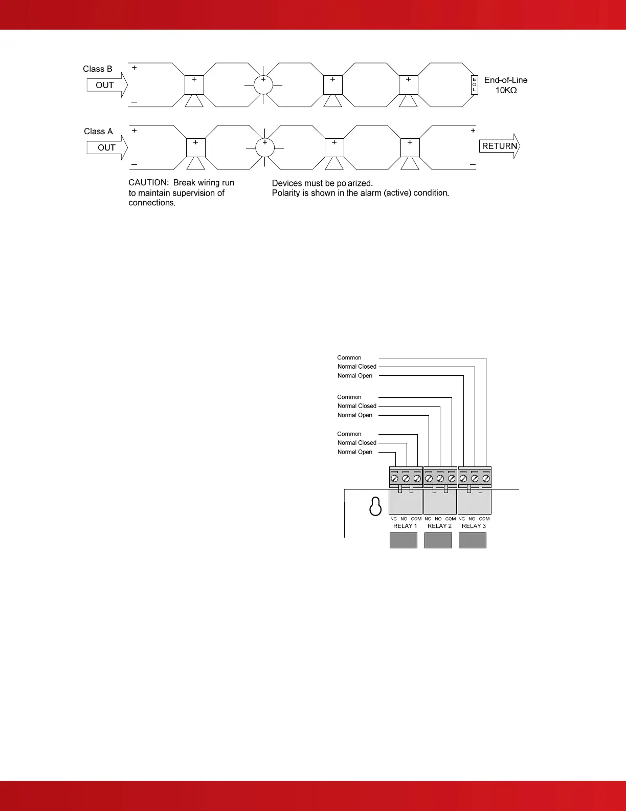
4.2.1.5 AX-CTL Relay Contacts
The AX-CTL provides three programmable Form C
relay contacts.
The contact ratings for each relay are as follows:
30 VDC/VAC @ 1.0A, PF=1 (resistive)
POWER LIMITED – Connect to power limited circuits
only.
Default operation is indicated below however, each
relay contact is field programmable.
RELAY 1: FIRE
RELAY 2: TROUBLE
RELAY 3: SUPERVISORY
The trouble relay contact is defaulted to normally
active (inverted) for fail-safe operation. The relay
transfers on any trouble condition including loss of
AC/DC power.
Wire range – 22-12 AWG
Note: Any relay of an AX-CTL fire alarm control
panel can be setup as a pulsed output and be
synchronized across the entire network.