www.advancedco.com
65
4.12.4 Replacing the Switch LED Module
Remove AC and DC power. Unplug the terminal block and/or 10-way IDC ribbon cables attached to the switch LED
module. Remove the nuts and washers holding the switch LED module to the inner door. Remove the switch LED
module and replace with the new switch LED module between the aperture screws and secure with the removed
nuts and washers. Replace the unplugged terminal block and/or 10-way IDC ribbon cables. Reconnect removed AC
and DC power.
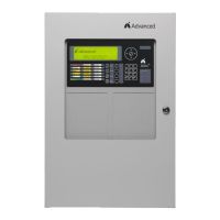
Figure 39 – Switch LED Module Wiring
24V
-+
485
B A
PSU
MONITOR
-+
1234567
ON
24V
-+
485
B A
PSU
MONITOR
-+
1234567
ON
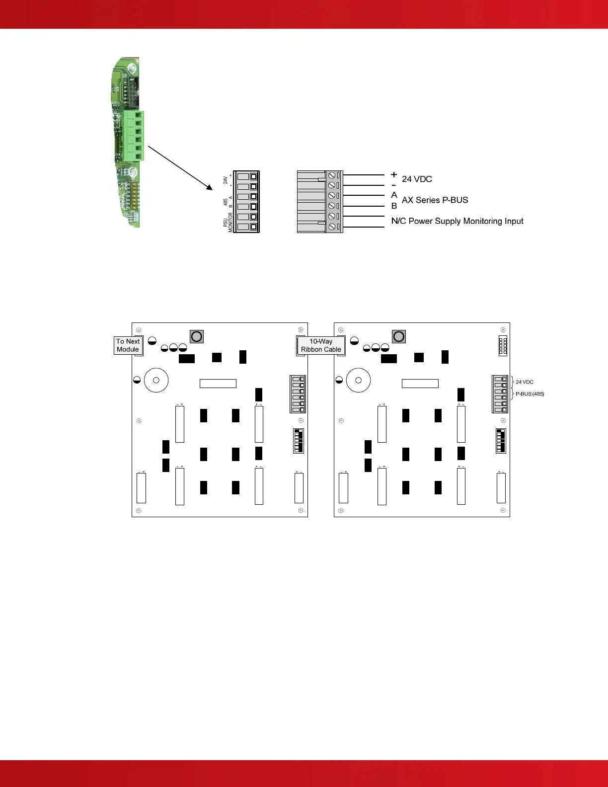
Figure 40 – Switch LED Module Daisy Chain Wiring