EasyManua.ls Logo

Advanced Axis AX-CTL-1L User Manual

Advanced Axis AX-CTL-1L
118 pages
To Next Page IconTo Next Page
To Previous Page IconTo Previous Page
Page #15 background image
www.advancedco.com
15
Must be
earthed
4.1.1 AX-ACB Electrical Specifications
AC Branch Circuit Ratings:
120V (1.4A [1 or 2 loop] / 2.8A [4 loop]) – 240V (0.7A [1 or 2
loop] / 1.4A [4 loop]) 50/60Hz
Brown-out – 98V nominal
15A Branch Circuit
Fuse: 5A, 250VAC Ceramic, Time Delay (size 5x20mm)
(Advanced part number 620-003, Bussmann S505-5-R,
Littelfuse 0215005.XP)
AC Wiring: #14 or #12 AWG, refer to NEC
Over-current protection for this circuit must comply with
Article 760 of the National Electrical Code (NEC) and/or
local codes.
The panel must be connected to a
solid earth ground. Use #14 AWG
(2.00 mm
2
) or larger wire with 600
volt insulation rating.
4.1.2 Replacing the AX-ACB AC Board
If replacing the AX-ACB AC board, remove power (AC and battery) from the system. Remove all Molex connector
plugs and the green ground wire plug from the AX-ACB board. Remove the four (4) screws holding the AX-ACB
board to the back box (see figure 4).
Place the new AX-ACB board over the four (4) mounting standoffs and secure with the four (4) removed screws.
Replace the removed Molex connector cables and green ground wire plug, and reconnect AC and battery power.
Failure to tighten the screws will defeat the protection circuitry designed to protect the module from
damage due to lightning and static electricity.
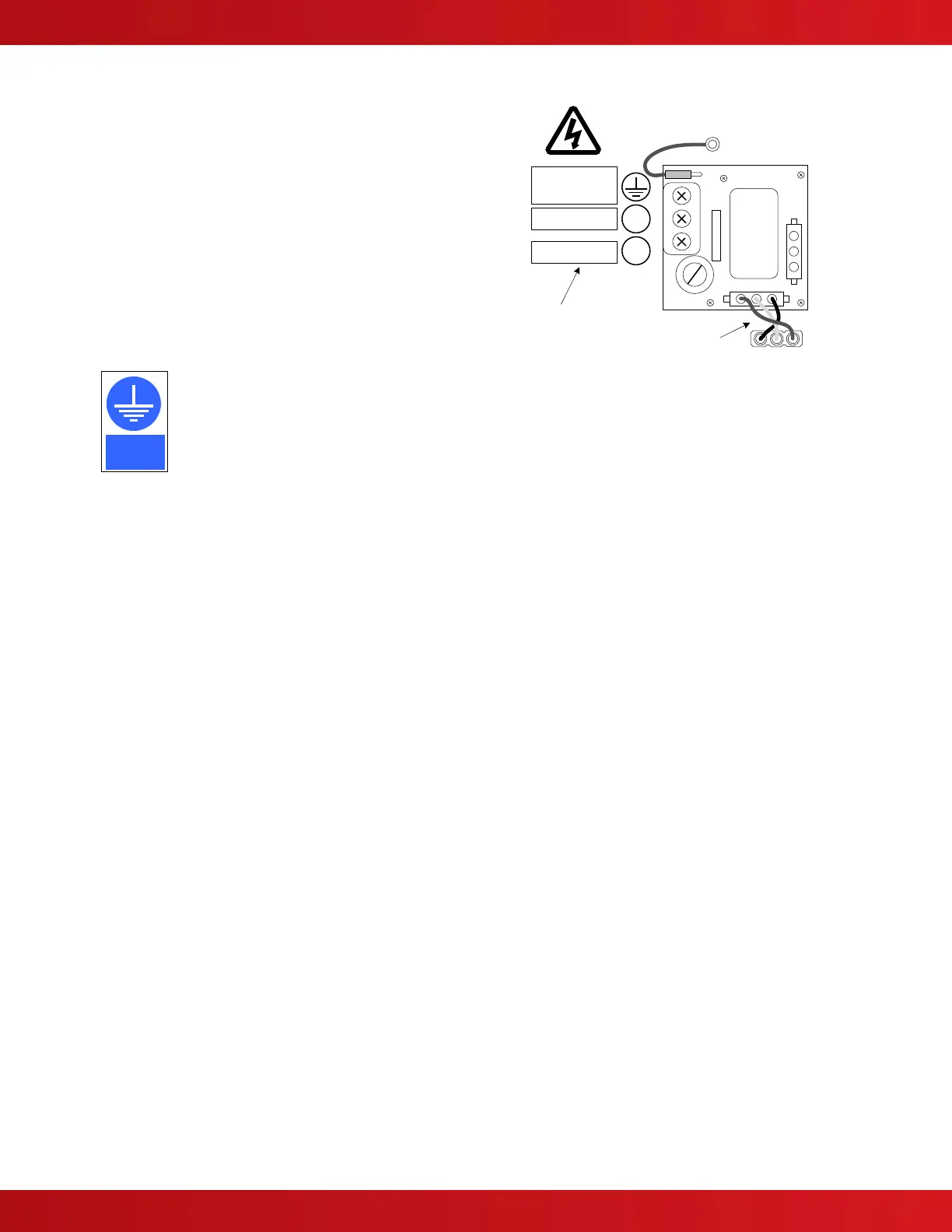
L
N
EARTH
GROUND
NEUTRAL
HOT/LIVE
AC Input
15A Branch Circuit
#14 or #12 AWG
Internal Cable
(pre-wired)
Ground Wire
(pre-wired to backbox stud)

Table of Contents

Questions and Answers:

Advanced Axis AX-CTL-1L Specifications

General IconGeneral
BrandAdvanced
ModelAxis AX-CTL-1L
CategorySecurity System
LanguageEnglish

Summary

1 Introduction and Overview

1.1 Product Description

Details the AX-CTL-1L, AX-CTL-2, AX-CTL-4 panels and their features.

1.4 General Installation Notes

Provides essential installation guidelines and precautions for the system.

2 Agency Listings and Requirements

2.1 ANSI/UL864

Product listing for various services and applications.

3 Enclosure Installation

3.1 Enclosure Mounting and Dimensions

Details enclosure mounting options and overall dimensions.

3.2 Inner Door Assembly

Covers inner door assembly and aperture modules.

4 Circuit Card Installation and Electrical Specifications

4.2 AX-CTL Base Card

Describes the main AX-CTL-1PCB/2PCB base card and its features.

4.3 AX-DSP Alphanumeric Graphical Display

Describes the user interface display and its input capabilities.

6 Loading Calculations

6.1 Panel Loading Calculations

Discusses load calculations for panel components and battery requirements.

7 Operation

7.1 User Controls and Indications

Explains panel controls (keys) and status LEDs.

7.2 LCD Indications

Describes panel display messages for various conditions.

7.8 User Menu Functions

Overview and description of user menu options.

9 AxisAX Wiring Guide

9.1 General Wiring Guidelines

Provides guidelines for circuit wiring types and distances.

10 Maintenance & Troubleshooting

10.1 Troubleshooting

General troubleshooting guidance for the system.

10.2 Replacement of Components

Procedures for replacing components like batteries and displays.