www.advancedco.com
27
Available in either single (AX-APS2-F1) or dual (AX-APS2-F2) action configuration, the AX-APS2-xx stations are
designed to prevent false alarms when bumped, jarred or shaken. The dual action AX-APS2-F2 further deters
malicious false alarms by requiring a two-process function for activation; first push the “PUSH” bar inwards which
then allows the “PULL” bar to be grasped and pulled outward.
Optional surface back boxes are available for indoor applications.
The Intelligent Manual Pull Stations are available in a variety of colors to meet various special application
requirements. Colored stations do not include the raised white “FIRE” labeling, but are capable of accommodating
labels for Alert, Alarm, Exit, Evac, etc. identification. Special applications can include; weather alert, door release,
medical emergency, fire suppression activation and others.
4.2.1.3.1.5.2 DualActionPolycarbonate56000‐005ADV
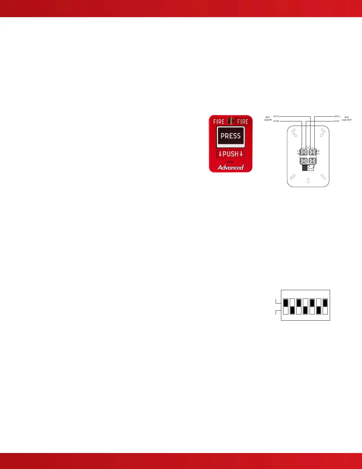
The Intelligent Dual Action Polycarbonate Pull Stations (56000-
005ADV) are low profile, high quality addressable manual pull
stations. Easily recognizable during a fire situation, the 56000-
005ADV station is constructed of rugged polycarbonate for long
life and reliability, with a red finish and raised white “FIRE”
lettering. A red LED visible through the face of the station
flashes during polling and turns on steady in alarm. Each
station includes a key-lock for resetting (CAT B / CAT 30) which
is common with the Axis
AX
fire alarm control panel.
The 56000-005ADV stations are UL 38 Listed, meet the ADAAG controls and
operating guidelines, and the ADA requirements for five pound maximum activation
force.
The 56000-005ADV, Intelligent Dual Action Polycarbonate Pull Station, can be mounted semi-flush onto a standard
single-gang electrical outlet box. If installations require surface mounting, an optional polycarbonate surface back
box (56000-006ADV) is available.
4.2.1.3.1.6 IntelligentModules
Intelligent Modules offer a wide range of input and output capabilities. The communications is a digital protocol that
provides a high degree of immunity to transient noise and interference. The protocol also provides a mechanism for
a device to place an alarm flag on the communications data stream, providing a fast response (priority - refer to
specific module options) so that the alarm condition is registered within 2 seconds.
As with Intelligent Smoke Detectors, any Intelligent Module can be allocated to SLC addresses 1 – 126. The analog
values returned by the devices are 4 (Trouble), 16 (Normal) and 64 (Alarm).
Each Intelligent Module; Inputs, Outputs and Pull Stations are individually addressed
using a DIP switch. Opposite is an example of a programming DIP switch for address 42,
below is a chart giving the settings for each address. In DIP switch packages containing
eight (8) switches, the eighth switch is for classification of wiring type [Class A or Class B]
(see figure 7).
ON
1
64
234567
16 328421
1
0
42