ACCEPTANCE TESTING
5-1-5
TEST PROCEDURES
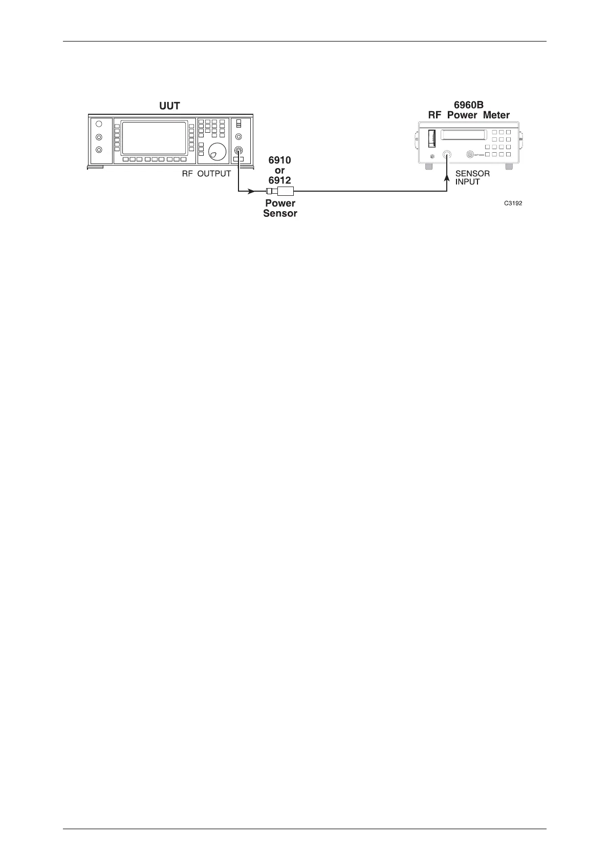
Fig. 5-1-1 RF output test set-up
(1) Connect the test equipment as shown in Fig. 5-1-1.
(2) Set the UUT to [RF Level] 0 dBm [Carrier Freq.] 30 kHz.
(3) Check that the output level is within specification at the frequencies shown in
Table 5-1-2.
When checking a 2032 signal generator, the 6912 sensor must be replaced with
6910 sensor for frequencies above 2700 MHz.
(4) Set the UUT RF output to 7 dBm and repeat (3) above.
(5) Set the UUT RF output to 13 dBm and repeat (3) above.
Table 5-1-2 Frequency settings for output levels
FREQUENCY (MHz)
(2030/1/2) 1125 2025 2925 4425
0.03 1275 2175 3075 4575
0.1 1350 2325 3225 4725
75 2475 3375 4875
225 (2031/2) 2625 3525 5025
375 1351 2700 3675 5175
525 1425 3825 5325
675 1575 (2032) 3975 5400
825 1725 2701 4125
975 1875 2775 4275
ALC linearity
(1) Connect the test equipment as shown in Fig. 5-1-1.
(2) Set the UUT to [RF Level] 0 dBm [Carrier Freq.] 2.5 MHz.
(3) Increment the RF output of the UUT in 1 dB steps up to 12 dBm and in 0.1 dBm
steps up to 13 dBm, measuring the RF level at each step. Check that the RF
output level variation is within ±0.1 dB.
(4) Set the UUT carrier frequency to 500 MHz and repeat (3) above.
(5) Set the UUT carrier frequency to 2.7 GHz and repeat (3) above.
(6) Replace the 6912 sensor with the 6910 sensor, set the UUT carrier frequency to
5.4 GHz and repeat (3) above.

 Loading...